Introduction
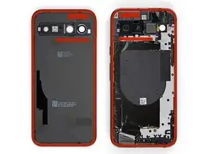
This guide shows how to remove the logic board in your Google Pixel 8a.
-
-
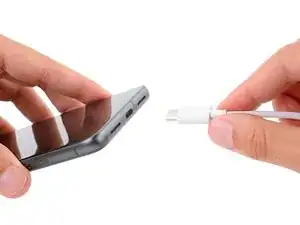
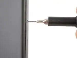
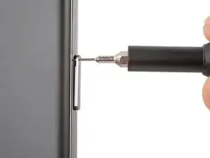
Firmly press a SIM eject tool, bit, or straightened paper clip into the SIM card tray hole on the left edge of your phone until the tray ejects.
-
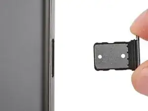
Remove the SIM card tray.
-
-
-
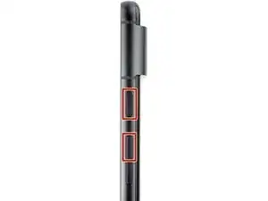
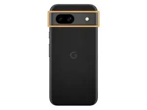
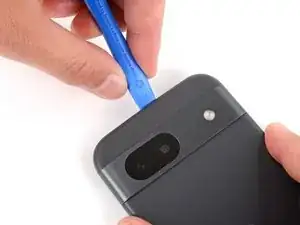
Unless stated otherwise, don't insert your tool more than 3 mm (the width of your opening tool's flat section) around the edges.
-
Don't insert your tool under the edges of the camera bump.
-
-
-
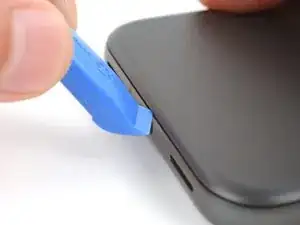
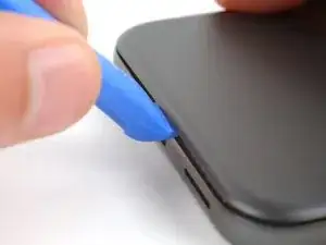
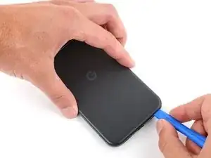
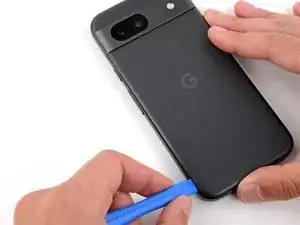
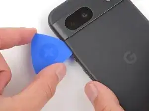
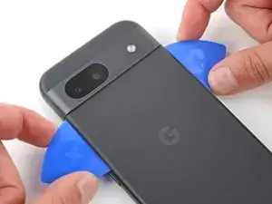
Insert the edge of an opening tool between the back cover and the frame, starting with a sharp corner of the tool to help separate the adhesive.
-
-
-
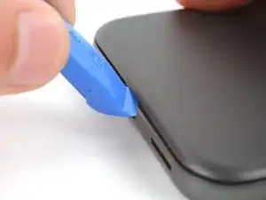
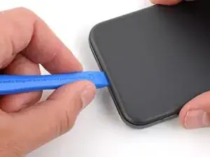
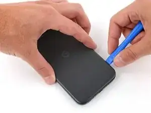
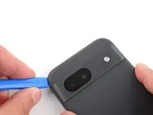
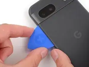
Slide your opening tool along the bottom edge to separate the adhesive securing the back cover.
-
-
-
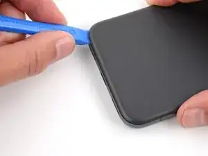
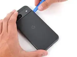
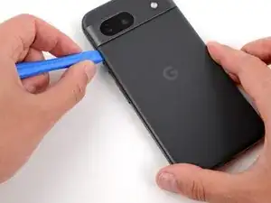
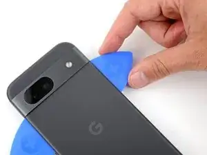
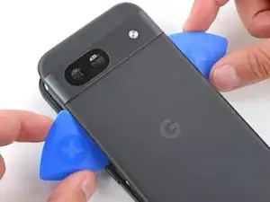
Slide your opening tool around the bottom right corner and up the right edge, stopping at the bottom of the camera bump.
-
Remove your opening tool from under the back cover.
-
-
-
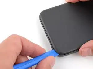
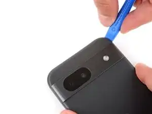
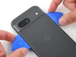
Insert your opening tool under the top right corner of the back cover, just above the camera bump.
-
Slide your opening tool along the top edge, stopping at the top left corner just above the camera bump.
-
Remove your opening tool from under the back cover.
-
-
-
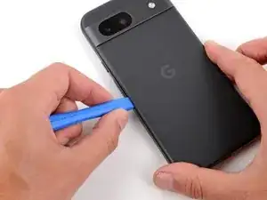
Insert your opening tool under the left edge of the back cover, just below the camera bump.
-
Slide your opening tool down the left edge to separate the adhesive.
-
-
-
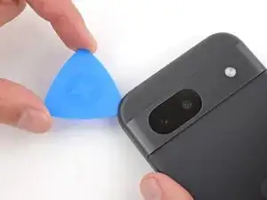
Insert an opening pick under the top left corner of the back cover until the tip is close to the top edge of the camera bump.
-
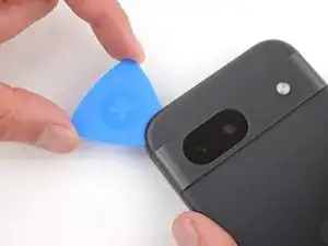
Slide the pick to the right, stopping when you reach the right edge of the cameras.
-
-
-
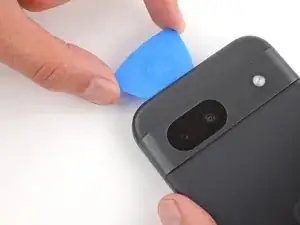
Insert the flat edge of an opening pick under the back cover, just below the camera bump.
-
Insert a second opening pick in the same spot on the other side.
-
-
-
Pry up simultaneously with both picks and apply constant pressure to separate the final piece of adhesive securing the back cover.
-
-
-
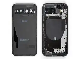
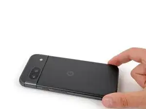
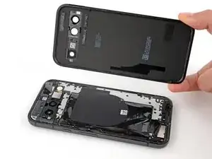
Remove the back cover.
-
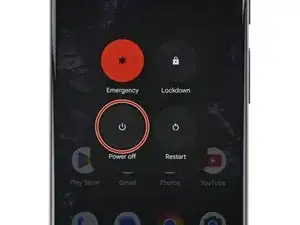
Now is a good time to test your phone before sealing it up. Power it on and check that it works. Power it back down before you continue reassembly.
-
Follow this guide to apply new adhesive and install your back cover.
-
-
-
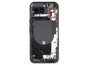
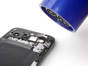
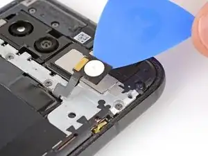
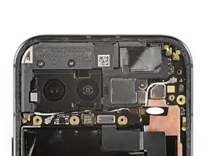
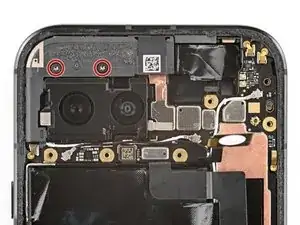
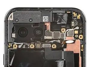
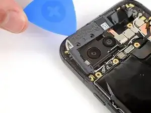
Use a hair dryer to heat the flash unit to soften the adhesive securing it to the logic board cover.
-
-
-
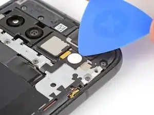
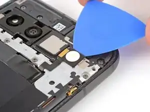
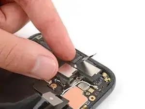
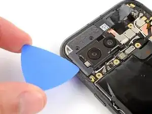
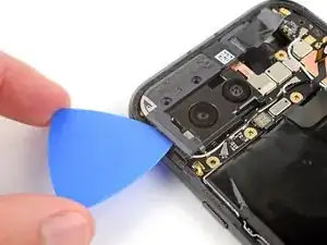
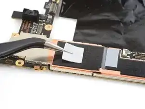
Slide your pick under the top edge of the flash and lift to separate the adhesive securing it to the cover.
-
-
-
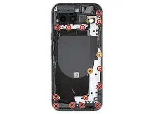
Use a Torx Plus 3IP screwdriver to remove the 15 screws securing the logic board cover:
-
Thirteen 4.3 mm‑long screws
-
Two 1.9 mm‑long screws
-
-
-
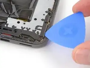
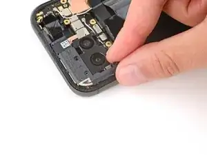
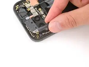
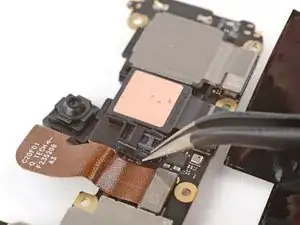
Insert an opening pick under the bottom right corner of the logic board cover and pry up to release the clip.
-
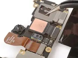
Insert the tip of a spudger under the notch near the top right corner of the logic board cover (just below the screw hole) and pry up to release the clip.
-
-
-
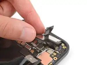
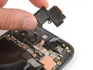
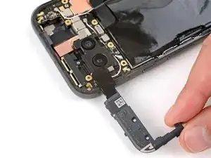
Slowly lift the top edge of the logic board cover and thread the flash unit through its cutout.
-
-
-
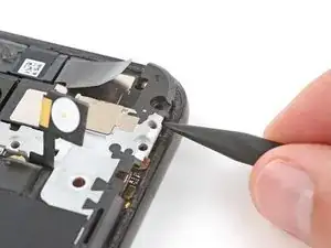
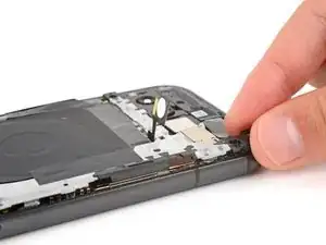
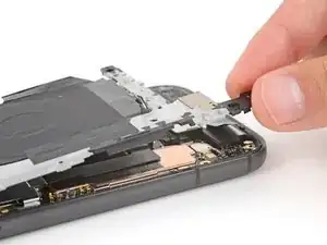
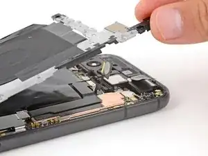
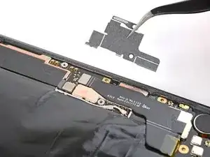
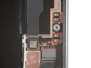
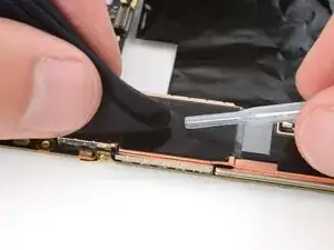
Use a pair of tweezers or your fingers to remove the metal cover on the right edge of your phone.
-
-
-
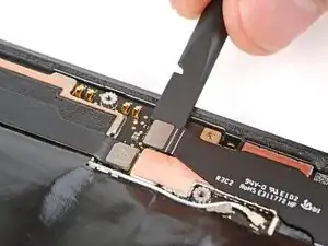
Insert the flat end of a spudger under the right edge of the battery press connector and pry straight up to disconnect it.
-
-
-
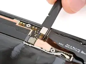
Insert the point of a spudger under the bottom edge of the 5G mmWave antenna press connector and pry straight up to disconnect it.
-
-
-
Use a Torx Plus 3IP screwdriver to remove the 4.3 mm‑long screw securing the earpiece speaker to the frame.
-
-
-
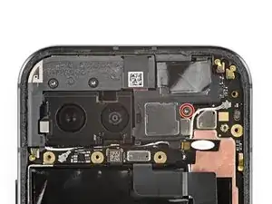
Use a Torx Plus 3IP screwdriver to remove the two 4.3 mm‑long screws securing the antenna housing.
-
-
-
Insert an opening pick under the left edge of the antenna housing and pry up to release the clips securing the housing.
-
Repeat the process on the top edge to release the remaining clips.
-
-
-
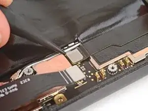
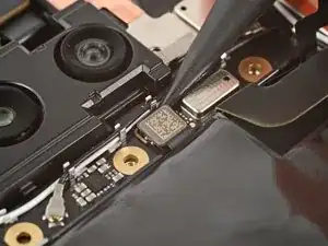
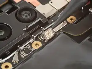
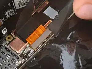
Use the point of a spudger or your fingernail to pry up and disconnect the press connector just above the battery.
-
-
-
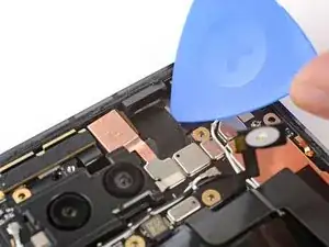
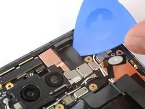
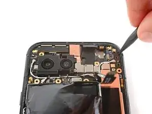
Slide the tip of your opening pick under the right edge of the front-facing camera cable and lift to detach it.
-
-
-
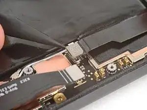
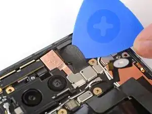
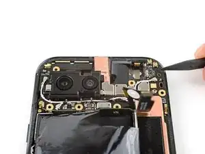
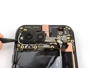
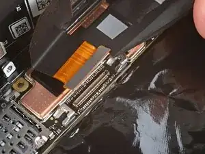
Insert the tip of a spudger under the notch near the top right corner of the logic board and pry up to unclip the board.
-
Repeat the process to unclip the other side of the board, using the notch to the left of the cameras.
-
-
-
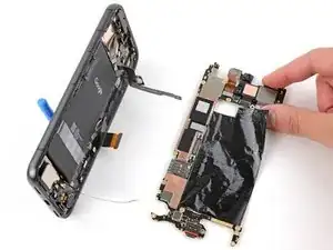
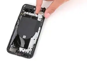
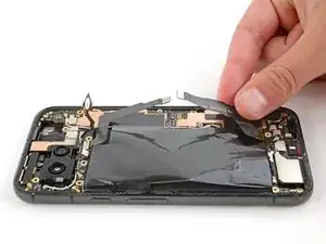
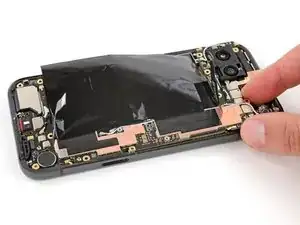
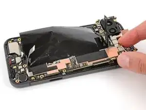
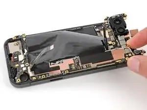
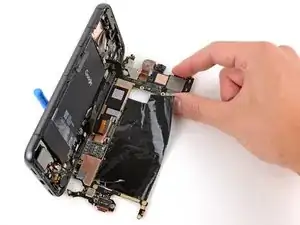
Lift the top edge of the logic board from the frame.
-
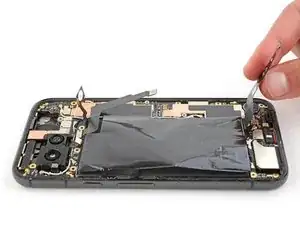
Pull the top edge of the logic board to the right of the frame so the cutouts of the board lift over the vibration motor and protrusions in the frame.
-
As you pull, guide the charging port out of its recess in the frame.
-
-
-
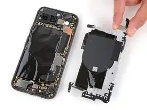
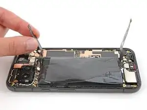
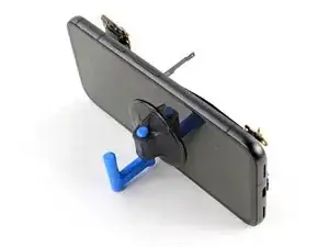
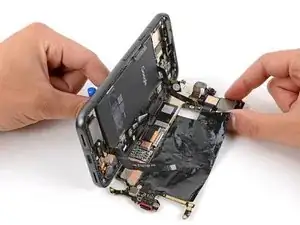
Apply a suction handle to the left side of the screen with the handle facing down.
-
Prop up the left side of your phone so it stands upright.
-
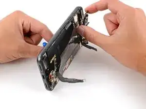
Tilt the logic board down and lay it flat, gently guiding the delicate graphite sheet around the cables.
-
-
-
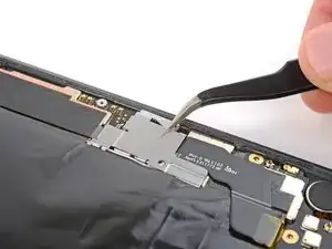
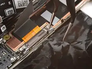
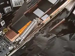
Use the tip of one arm of your angled tweezers to pry up the top edge of the display cable bracket from the center of the logic board.
-
Remove the bracket.
-
-
-
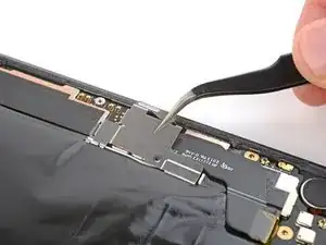
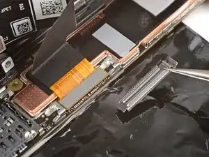
Insert the flat end of a spudger or a clean fingernail under the top edge of the display cable press connector and pry straight up to disconnect it.
-
-
-
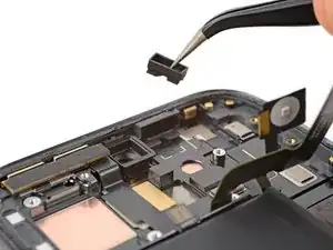
If the front sensor rubber gasket stayed on the frame or became misaligned, remove it and set it aside.
-
-
-
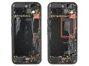
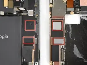
Check the condition of the thermal pads—they'll be on the bottom of the logic board or the corresponding spot on the right side of the frame.
-
If you're reusing your logic board and either of the thermal pads are damaged, remove the old pad, clean the surface with highly-concentrated isopropyl alcohol (over 90%), and apply a new pad.
-
If you have a new logic board and it doesn't come with thermal pads pre-installed, apply the new pads now.
-


To reassemble your device, follow these instructions in reverse order.
