Introduction
This repair guide was authored by the iFixit staff and hasn’t been endorsed by Google. Learn more about our repair guides here.
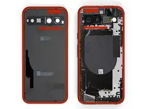
Follow this guide to replace the vibration motor, also known as the vibrator, in your Google Pixel 8a.
If your phone doesn't vibrate anymore, or the vibrations suddenly feel weaker, your vibration motor might need a replacement.
You'll need replacement back cover and flash unit adhesives to complete this repair.
Note: Any repair can compromise the water resistance of your phone. Retaining water resistance after the repair will depend on how well you reapply the back cover adhesive.
Tools
-
-
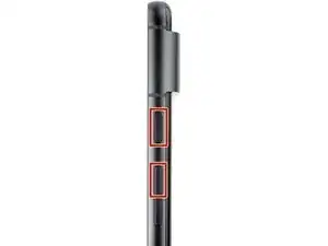
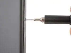
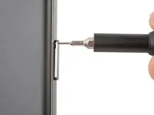
Firmly press a SIM eject tool, bit, or straightened paper clip into the SIM card tray hole on the left edge of your phone until the tray ejects.
-
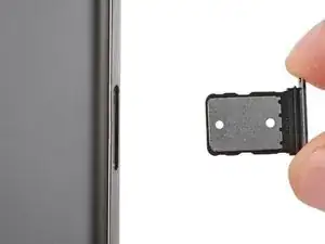
Remove the SIM card tray.
-
-
-
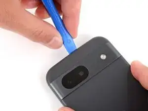
Unless stated otherwise, don't insert your tool more than 3 mm (the width of your opening tool's flat section) around the edges.
-
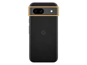
Don't insert your tool under the edges of the camera bump.
-
-
-
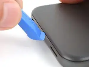
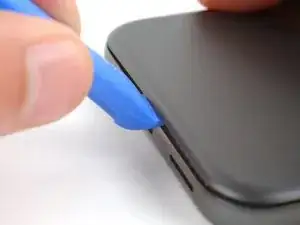
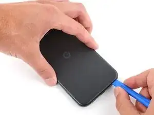
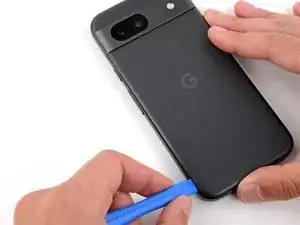
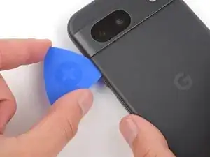
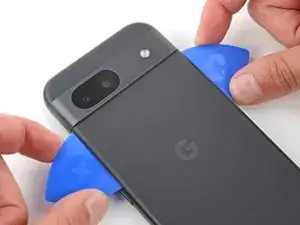
Insert the edge of an opening tool between the back cover and the frame, starting with a sharp corner of the tool to help separate the adhesive.
-
-
-
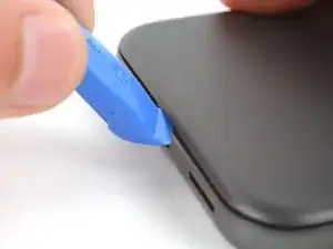
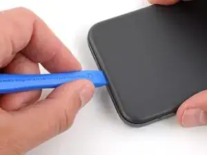
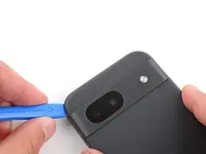
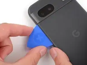
Slide your opening tool along the bottom edge to separate the adhesive securing the back cover.
-
-
-
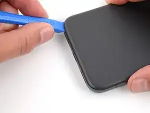
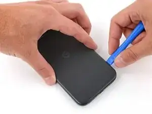
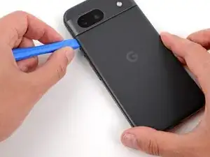
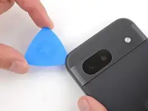
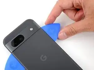
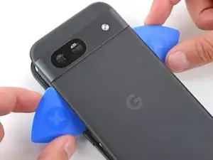
Slide your opening tool around the bottom right corner and up the right edge, stopping at the bottom of the camera bump.
-
Remove your opening tool from under the back cover.
-
-
-
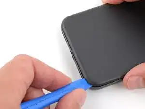
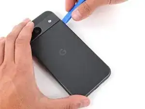
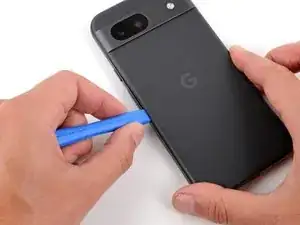
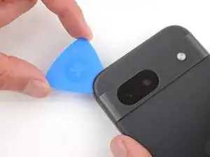
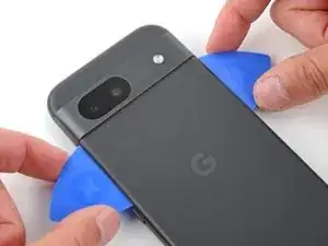
Insert your opening tool under the top right corner of the back cover, just above the camera bump.
-
Slide your opening tool along the top edge, stopping at the top left corner just above the camera bump.
-
Remove your opening tool from under the back cover.
-
-
-
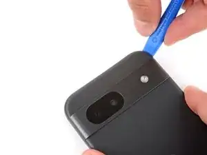
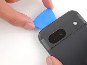
Insert your opening tool under the left edge of the back cover, just below the camera bump.
-
Slide your opening tool down the left edge to separate the adhesive.
-
-
-
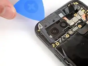
Insert an opening pick under the top left corner of the back cover until the tip is close to the top edge of the camera bump.
-
Slide the pick to the right, stopping when you reach the right edge of the cameras.
-
-
-
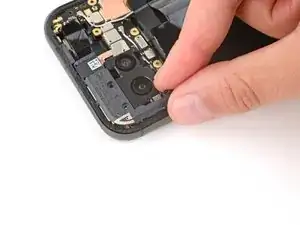
Insert the flat edge of an opening pick under the back cover, just below the camera bump.
-
Insert a second opening pick in the same spot on the other side.
-
-
-
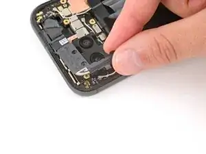
Pry up simultaneously with both picks and apply constant pressure to separate the final piece of adhesive securing the back cover.
-
-
-
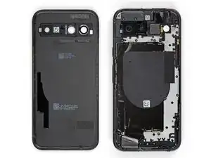
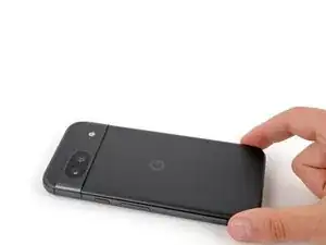
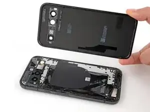
Remove the back cover.
-
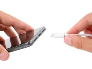
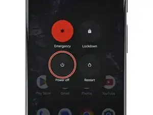
Now is a good time to test your phone before sealing it up. Power it on and check that it works. Power it back down before you continue reassembly.
-
Follow this guide to apply new adhesive and install your back cover.
-
-
-
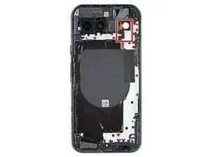
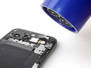
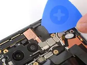
Use a hair dryer to heat the flash unit to soften the adhesive securing it to the logic board cover.
-
-
-
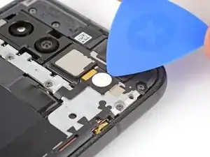
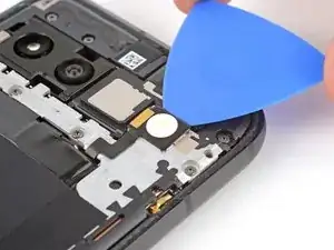
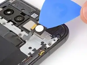
Slide your pick under the top edge of the flash and lift to separate the adhesive securing it to the cover.
-
-
-
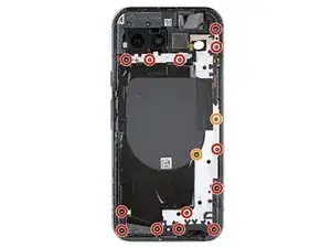
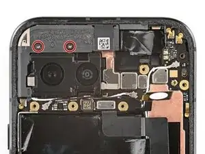
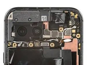
Use a Torx Plus 3IP screwdriver to remove the 15 screws securing the logic board cover:
-
Thirteen 4.3 mm‑long screws
-
Two 1.9 mm‑long screws
-
-
-
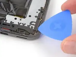
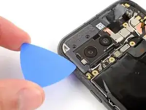
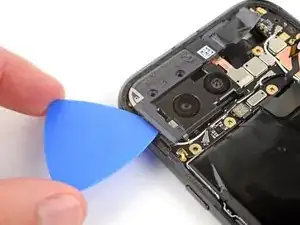
Insert an opening pick under the bottom right corner of the logic board cover and pry up to release the clip.
-
Insert the tip of a spudger under the notch near the top right corner of the logic board cover (just below the screw hole) and pry up to release the clip.
-
-
-
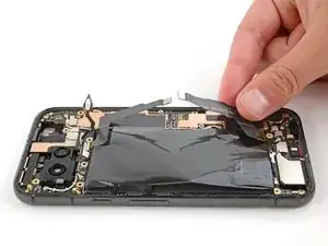
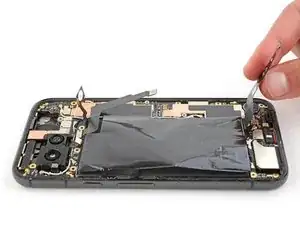
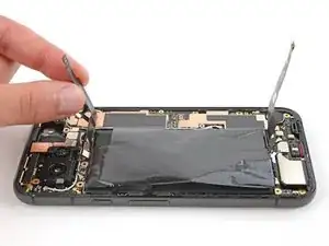
Slowly lift the top edge of the logic board cover and thread the flash unit through its cutout.
-
-
-
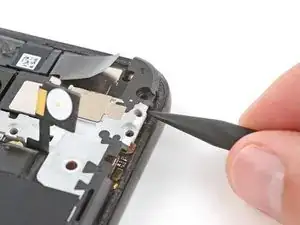
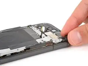
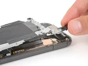
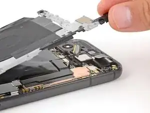
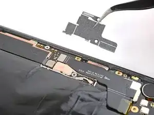
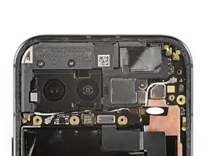
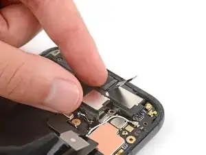
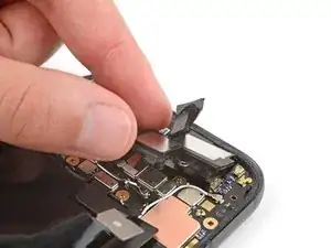
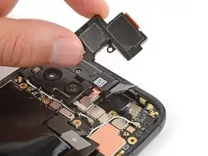
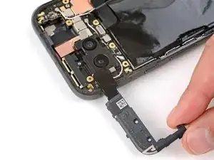
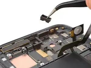
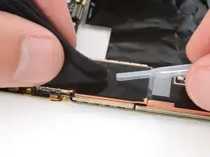
Use a pair of tweezers or your fingers to remove the metal cover on the right edge of your phone.
-
-
-
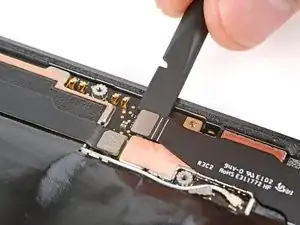
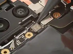
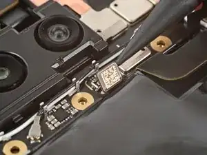
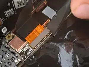
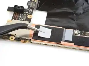
Insert the flat end of a spudger under the right edge of the battery press connector and pry straight up to disconnect it.
-
-
-
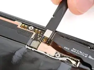
Insert the point of a spudger under the bottom edge of the 5G mmWave antenna press connector and pry straight up to disconnect it.
-
-
-
Use a Torx Plus 3IP screwdriver to remove the 4.3 mm‑long screw securing the earpiece speaker to the frame.
-
-
-
Use a Torx Plus 3IP screwdriver to remove the two 4.3 mm‑long screws securing the antenna housing.
-
-
-
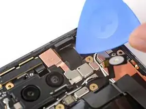
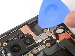
Insert an opening pick under the left edge of the antenna housing and pry up to release the clips securing the housing.
-
Repeat the process on the top edge to release the remaining clips.
-
-
-
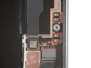
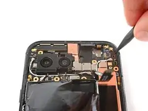
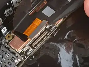
Use the point of a spudger or your fingernail to pry up and disconnect the press connector just above the battery.
-
-
-
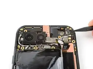
Slide the tip of your opening pick under the right edge of the front-facing camera cable and lift to detach it.
-
-
-
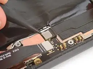
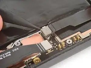
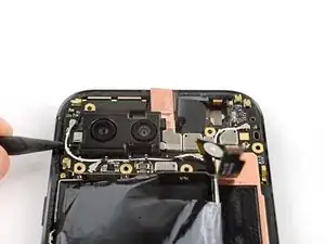
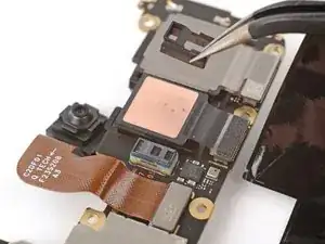
Insert the tip of a spudger under the notch near the top right corner of the logic board and pry up to unclip the board.
-
Repeat the process to unclip the other side of the board, using the notch to the left of the cameras.
-
-
-
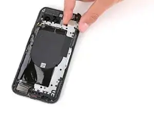
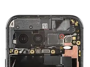
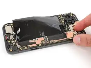
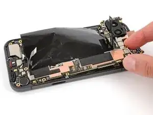
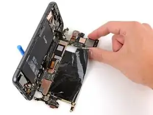
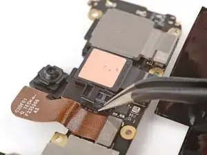
Lift the top edge of the logic board from the frame.
-
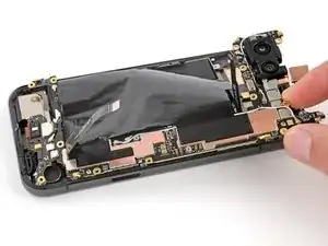
Pull the top edge of the logic board to the right of the frame so the cutouts of the board lift over the vibration motor and protrusions in the frame.
-
As you pull, guide the charging port out of its recess in the frame.
-
-
-
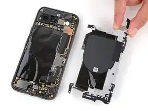
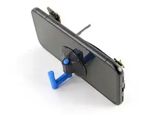
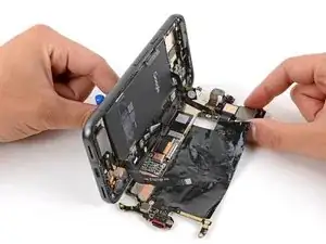
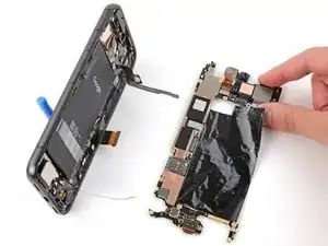
Apply a suction handle to the left side of the screen with the handle facing down.
-
Prop up the left side of your phone so it stands upright.
-
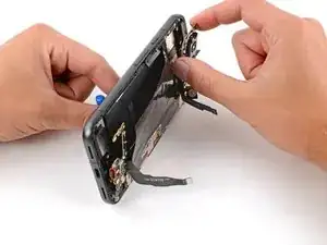
Tilt the logic board down and lay it flat, gently guiding the delicate graphite sheet around the cables.
-
-
-
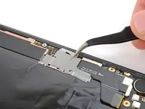
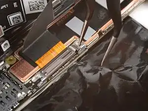
Use the tip of one arm of your angled tweezers to pry up the top edge of the display cable bracket from the center of the logic board.
-
Remove the bracket.
-
-
-
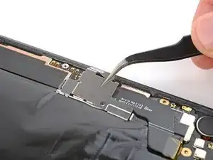
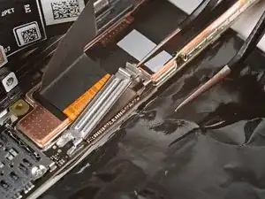
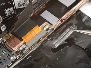
Insert the flat end of a spudger or a clean fingernail under the top edge of the display cable press connector and pry straight up to disconnect it.
-
-
-
If the front sensor rubber gasket stayed on the frame or became misaligned, remove it and set it aside.
-
-
-
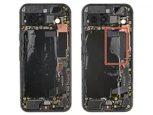
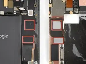
Check the condition of the thermal pads—they'll be on the bottom of the logic board or the corresponding spot on the right side of the frame.
-
If you're reusing your logic board and either of the thermal pads are damaged, remove the old pad, clean the surface with highly-concentrated isopropyl alcohol (over 90%), and apply a new pad.
-
If you have a new logic board and it doesn't come with thermal pads pre-installed, apply the new pads now.
-
-
-
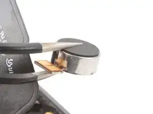
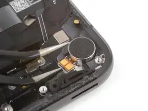
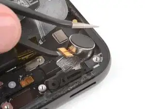
Slide one arm of a pair of angled tweezers under the vibration motor and lift to separate its adhesive.
-
-
-
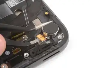
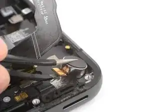
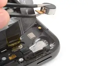
Remove the vibration motor.
-
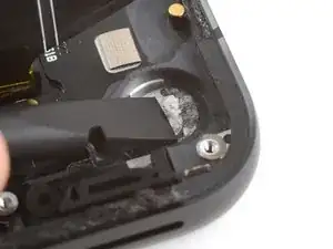
Use a spudger or tweezers to remove any old adhesive from the frame.
-
Remove any liners from your new vibration motor and press it into place.
-

To reassemble your device, follow these instructions in reverse order.
To run a diagnostics test with the built-in Pixel Diagnostic tool, click here.
Take your e-waste to an R2 or e-Stewards certified recycler.
Repair didn’t go as planned? Try some basic troubleshooting, or ask our Answers community for help.
