Introduction
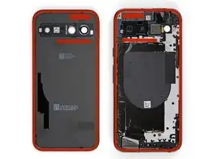
This guide demonstrates how to disconnect the battery in your Google Pixel 8a.
-
-
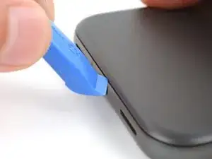
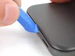
Unless stated otherwise, don't insert your tool more than 3 mm (the width of your opening tool's flat section) around the edges.
-
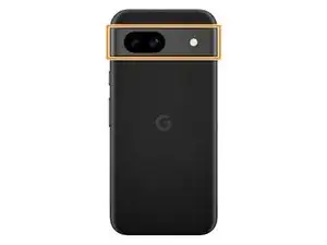
Don't insert your tool under the edges of the camera bump.
-
-
-
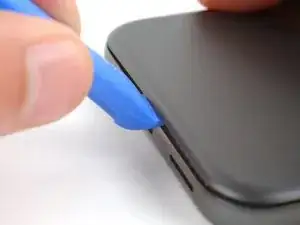
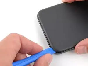
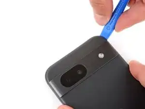
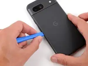
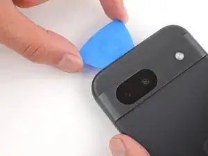
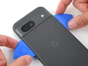
Insert the edge of an opening tool between the back cover and the frame, starting with a sharp corner of the tool to help separate the adhesive.
-
-
-
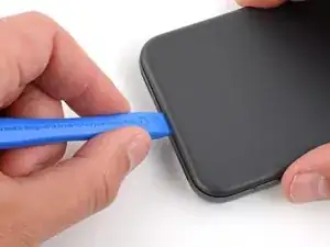
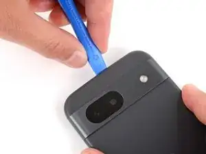
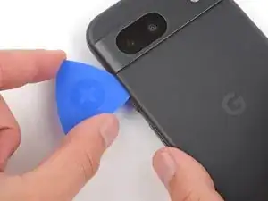
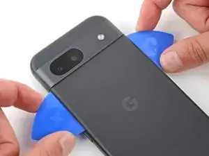
Slide your opening tool along the bottom edge to separate the adhesive securing the back cover.
-
-
-
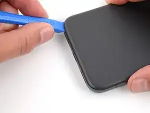
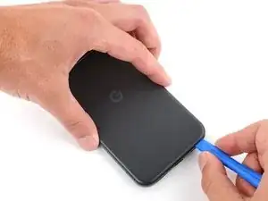
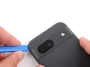
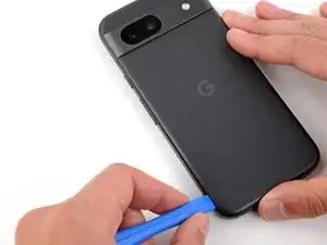
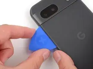
Slide your opening tool around the bottom right corner and up the right edge, stopping at the bottom of the camera bump.
-
Remove your opening tool from under the back cover.
-
-
-
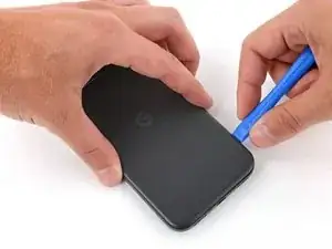
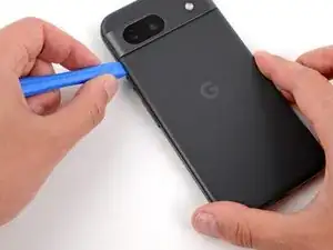
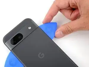
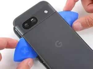
Insert your opening tool under the top right corner of the back cover, just above the camera bump.
-
Slide your opening tool along the top edge, stopping at the top left corner just above the camera bump.
-
Remove your opening tool from under the back cover.
-
-
-
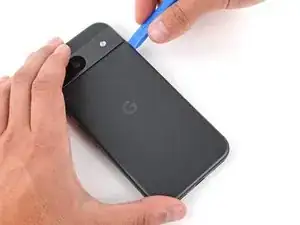
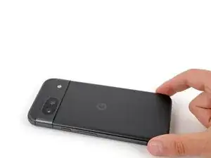
Insert your opening tool under the left edge of the back cover, just below the camera bump.
-
Slide your opening tool down the left edge to separate the adhesive.
-
-
-
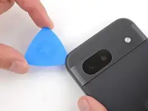
Insert an opening pick under the top left corner of the back cover until the tip is close to the top edge of the camera bump.
-
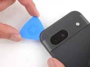
Slide the pick to the right, stopping when you reach the right edge of the cameras.
-
-
-
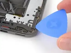
Insert the flat edge of an opening pick under the back cover, just below the camera bump.
-
Insert a second opening pick in the same spot on the other side.
-
-
-
Pry up simultaneously with both picks and apply constant pressure to separate the final piece of adhesive securing the back cover.
-
-
-
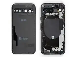
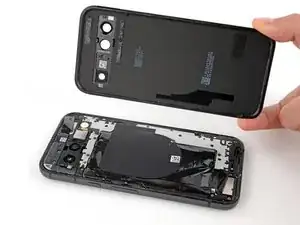
Remove the back cover.
-
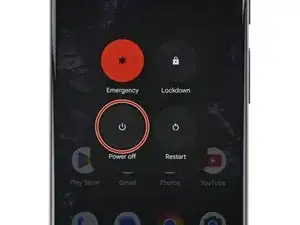
Now is a good time to test your phone before sealing it up. Power it on and check that it works. Power it back down before you continue reassembly.
-
Follow this guide to apply new adhesive and install your back cover.
-
-
-
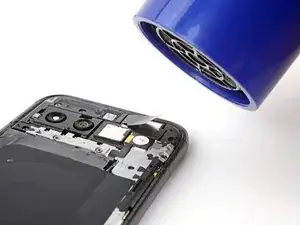
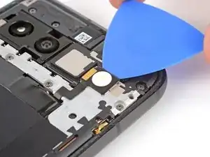
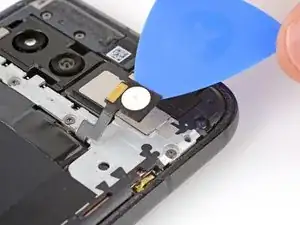
Use a hair dryer to heat the flash unit to soften the adhesive securing it to the logic board cover.
-
-
-
Slide your pick under the top edge of the flash and lift to separate the adhesive securing it to the cover.
-
-
-
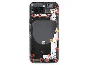
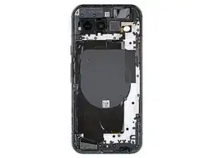
Use a Torx Plus 3IP screwdriver to remove the 15 screws securing the logic board cover:
-
Thirteen 4.3 mm‑long screws
-
Two 1.9 mm‑long screws
-
-
-
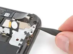
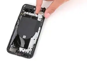
Insert an opening pick under the bottom right corner of the logic board cover and pry up to release the clip.
-
Insert the tip of a spudger under the notch near the top right corner of the logic board cover (just below the screw hole) and pry up to release the clip.
-
-
-
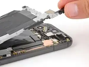
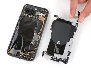
Slowly lift the top edge of the logic board cover and thread the flash unit through its cutout.
-
-
-
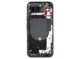
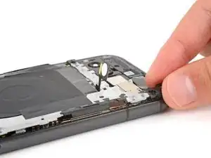
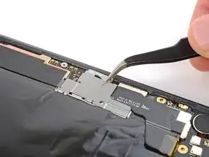
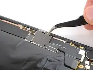
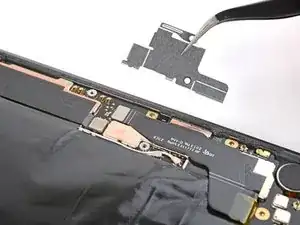
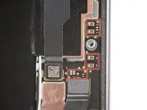
Use a pair of tweezers or your fingers to remove the metal cover on the right edge of your phone.
-
-
-
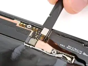
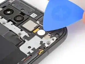
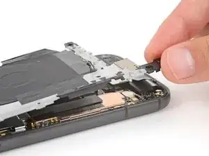
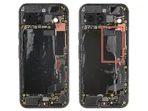
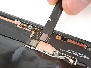
Insert the flat end of a spudger under the right edge of the battery press connector and pry straight up to disconnect it.
-


To reassemble your device, follow these instructions in reverse order.
