
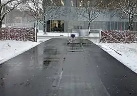
A snowmelt system prevents the build-up of snow and ice on cycleways, walkways, patios and roadways, or more economically, only a portion of the area such as a pair of 2-foot (0.61 m)-wide tire tracks on a driveway or a 3-foot (0.91 m) center portion of a sidewalk, etc. It is also used to keep entire driveways and patios snow free in snow prone climates. The "snow melt" system is designed to function during a storm to improve safety and eliminate winter maintenance labor including shoveling, plowing snow and spreading de-icing salt or traction grit (sand). A snowmelt system may extend the life of the concrete, asphalt or under pavers by eliminating the use of salts or other de-icing chemicals, and physical damage from winter service vehicles. Many systems are fully automatic and require no human input to maintain a snow/ice-free horizontal surface.
Systems are available in three broad types based on the heat source: electric resistance heat, heat from a conventional boiler (or furnace), or geothermal heat hydronically (in a fluid). Arguably, electric snowmelt systems requires less maintenance than hydronic snowmelt systems because there are minimal moving parts and no corroding agents. However, electric snowmelt systems tend to be much more expensive to operate.
Most new snowmelt systems operate in conjunction with an automatic activation device that will turn the system on when it senses precipitation and freezing temperatures, and turn the system off when temperatures are above freezing. These types of devices ensure the system is only active during useful periods and reduce energy waste. A high-limit thermostat further increases efficiency when installed in conjunction with the automatic snow melt controller to temporarily disable the system once the slab/surface has reached a sufficient snow melting temperature. Some building codes require the high-limit thermostat to prevent energy waste. Total environmental impact depends on the energy source used.
Electric snowmelt systems
Electric snowmelt systems are composed of three basic components: heating cable, a control unit and an activation device.
The heating cable is built to withstand harsh conditions to make it suitable for outdoor usage. The cable should be listed to UL standards by a Nationally Recognized Testing Laboratory and many consist of a single or dual conductor with a protective coating and/or insulation. Many cables are rated at 105 °C (221 °F) and produce 6–50 watts per foot. Power per area is determined by heating element spacing.
The control units are typically wall-mounted control panels and can be mounted in a NEMA enclosure. Control units vary by technology by using line and load terminal blocks, relays, activation terminals, transformers, as well as monitoring electronics.

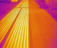
In recent years a new technology [1] [2] has been developed to address melting snow on asphalt surfaces. Although asphalt pavements are the most common pavement type worldwide, there is no accepted heating solution for this infrastructure class for melting snow and preventing ice formation at the ride-surface. This novel methodology is utilizing electric ribbon technology as a suitable heating solution. A new method was proposed to introduce ribbon heaters into the typical paving process in a practical manner, causing minimal disruption to the normal paving operations, that is potentially expandable to large areas. The advocated idea was to deploy ribbons after an asphalt concrete lift has been paved and compacted, and before paving and compacting the next asphalt concrete lifts. In this context, a special grooving machine was envisioned to make shallow channels in the asphalt for cradling each ribbon. Thus, the system survivability is guaranteed, with all ribbons protected against the maneuvering of trucks, paving equipment, and heavy rollers. Subsequently, the method was demonstrated through the full-scale construction of a heated road that included installing ribbons in-between asphalt concrete lifts. For this purpose, the protective ribbon channels were grooved with a customized milling machine.
Hydronic snowmelt systems
The heating element in a hydronic system is a closed-loop tubing or modular thermapanel system made of a flexible polymer or synthetic rubber that circulates a mixture of hot water and propylene glycol (antifreeze). The fluid is warmed to temperatures of 16 °C (61 °F) to 60 °C (140 °F) to warm surrounding concrete/asphalt/concrete pavers and melt snow and ice. Mechanical system technology for hydronic snowmelt systems is based on the same technology as radiant heating systems.
The most crucial part of a successful tube based hydronic heating system depends on proper tube spacing and layout. It is recommended to lay the tubes in a spiral or serpentine pattern to help distribute the heat evenly. Specification for spacing will vary between manufacturers. A faster rate of snowmelting will require closer spacing of tubing, typical spacing is 6-8". Another key factor is the amount of insulation used under the slab.
Hydronic tubes that are cast into concrete slabs will create an uneven heating pattern in the concrete thus causing uneven stresses to occur within the concrete slab. The use of high temperature fluid entering a very cold slab will create stress cracks and possible spalling of the concrete surface. Close tube spacing and a controlled slow increase in temperature will lessen the negative effects of a tube based system. Another method is to maintain a minimum slab temperature above freezing throughout the winter season.
An alternative to tube based systems is pre-insulated, HDPE modular heat exchange thermal panel units. The HDPE modular panels fit pedestal mounted pavers (typically used on rooftop installations) in a modular grid layout of between 23.5" - 26" on center. They may also be used with any type of ground mounted, cast in place concrete or raised deck mounted pavers, wood or PVC decking.
Like electric snowmelt systems, hydronic snowmelt systems may be installed in or beneath the base surface material (sand). The subgrade should be well compacted with an appropriate road base material that meets ICPI (International Concrete Paver Institute) or the paver manufacturer's guidelines before beginning tube or thermapanel installation. Uneven settlement may damage the system and provide a structurally weak pavement. Tubing can be fastened with cable ties to either the re-mesh, rebar or stapled to below slab insulation. Insulated modular thermapanel systems do not require re-mesh or rebar and are laid out in pre-connected rows onto the compacted sub-base. When a modular thermapanel system is set under a concrete slab, re-mesh or rebar within the concrete monolith may be necessary.
Hydronic tubes should not be placed directly on top of solid bedrock; this will cause the heating tubes to conduct heat into the earth. Pre-insulated modular thermapanel systems can be laid directly on bedrock or a structural concrete base.
To comply with most paver manufacturers warranties and ICPI (International Concrete Paver Institute) specifications, up to 1" of bedding sand for the pavers should be used and shall not exceed a maximum of 1 1/2". This can be a challenge with tube and re-bar based systems as they typically require over 1 1/2" of bedding sand. Excessive bedding sand will cause the pavers to settle over time. The sand used for bedding and jointing should be clean concrete sand, free of clay, dirt, or foreign matter and should conform to ASTM C-33.
Modular, fluid thermal transfer panel systems provide full and even heat exchange with the entire paver or concrete area as opposed to the spacing required by a tube based system. Full coverage allows for the use of lower temperature fluid which lowers the operating cost and lessens the thermal impact to the pavement structure thus reducing the deterioration of the concrete surface. The surface also comes up to temperature and can be cooled quicker.
Modular snowmelt systems can also be used to collect solar thermal energy from the pavement on warm days for the heating of pools and domestic or industrial purposes. They may also be utilized to cool the pavement surface, particularly around swimming pools or on pedestal mounted rooftop paver terraces which get very hot due to the paver being uncoupled from the building thus creating a solar battery which in turn increases the urban heat island effect in the immediate vicinity.
Operation costs
Operating costs vary by region, energy source (electric, gas, propane, etc.) used and costs associated. The American Society of Heating, Refrigerating and Air-Conditioning Engineers has standards intended to achieve satisfactory results and to minimize energy consumption from over-sizing or over-designing a system. Systems are typically designed to produce 70–170 BTU per square foot hour using ASHRAE guidelines by region. The time to melt snow from a surface varies by storm and how much power the system is designed to produce.
Activation devices
There are a number of activation devices used for snow melting applications. Some activators are a simple manual timer that activate the system to stay on for a specified time period while others sense temperature and moisture or just temperature conditions to automatically activate the snow melt system. Automatic devices can be aerial-mounted, pavement mounted or gutter mounted. High-end activation devices feature adjustable temperature trigger points, adjustable delay off cycle, and upgradeable remote activation. The activation device enables the snowmelt system to run 100% automated.
Self-regulating trace heating cables automatically regulate the amount of heat supplied so that only those parts with temperatures below the set point are heated.
Careful placement of the sensors is important to have an effective result when using these activators. Activation moisture sensors should be placed in a location where they will effectively collect any moisture from a snow storm and in relatively close proximity to the area to be free of snow and ice. Temperature sensors are installed outside to sense the same temperature conditions that the surface that the snow melting system will experience. Other activators, such as manual timers or switches can be installed in a convenient location.
New installations
The installation of snow melt systems is accomplished during construction of the walkway or roadway with the spacing of the cables or tubing or the layout of the modular thermapanel rows based on the system design.
There should be a minimum of 3” and max 4” of substrate covering the electric heating cables for new concrete applications. Concrete mixture must not contain sharp stones as these may damage the cable. The concrete should be allowed to set for 30 days before the heating cables are turned on. For this reason, the best installation time is during summer months. There is no practical way to use electric cable systems with pedestal mounted pavers.
Tubing systems typically have the tubes attached to the structural reinforcement which are then aligned within the concrete slab using cribs or standoffs. There is no practical way to use tubing based systems with segmented pavers or pedestal mounted pavers. The only type of hydronic system currently commercially available for use with pedestal, platform or ground mounted pavers is a modular thermapanel type system.
System installation specifications beneath asphalt may vary between each manufacturer. The cable can be laid out on the base surface (usually a sand bed), and covered with 1/2" sand. The asphalt is then hand-shoveled onto the heating cable and base surface.
When installing a hydronic tube or thermapanel system beneath asphalt, a barrier of sand that meets the manufacturers specifications should be placed over the tubing or thermapanels and cold water should be pumped through the system to keep the plastic from melting.
Insulation below the cables or tubing is recommended, but not required. One-inch rigid insulation can be installed underneath the base surface, or it can be laid on the base surface and the heating cable can be secured on top of the insulation.
Some installations involve two layers of asphalt. For this installation, a base layer of asphalt (1" thick) is placed down first. Heating cables are then installed and secured to the surface of the base layer. Once the heating cables are installed, a second layer of asphalt is placed over the heating cables and the first layer, embedding the heating cables within the slab.
Installing a snowmelt system under brick pavers is achieved by placing the heating cables on the base surface over 1/2" of sand. The heating cables are then covered with 1/2" of sand and the pavers are installed as normal over the sand bed. When using a hydronic system, up to 1" of bedding sand shall be placed over the thermapanel units. Tubing is not recommended for segmented paving applications due to the need for excessive bedding sand.
Retrofit installations
Retrofit installations are possible with electric systems by cutting grooves 11⁄4" to 11⁄2" deep and between 1/4" and 3/8" wide into the asphalt or concrete, inserting the cables and sealing the grooves with backer rod and a special caulking or sealant at the surface of the groove.
Portable heated snow mats for consumers
Within the past few years, heated snow melting mats have become available to retail consumers. These plug into a water-resistant electrical outlet, and can be laid on walkways, driveways, stairways, wheelchair ramps, and loading docks.[3]
These heated mats consist of two layers of slip-resistant rubber with an intervening heating element, and can melt snow and ice in hours or minutes (depending on heat level and snow level). The mats turn on below a preset temperature with an optional inline thermostat.
Notable installations
- Maxima Hospital, Eindhoven, The Netherlands.[4]
- Truck Loading Docks, Eindhoven, The Netherlands.[5]
- Under-road heating system to keep Europe’s highways ice-free[6]
- Elevated Central Artery, Boston (disused and since demolished)[7]
- M4 motorway, West London (disused)
- Schweitzer Mountain roads, Idaho
- Former personal residence of Peter Lawwell, driveway
- Updown Court driveway, England
- Bill Gates' house, driveways
- Public sidewalks in Reykjavík and Akureyri, Iceland[8][9]
- Karl Johans gate and various public sidewalks in Oslo, Norway[10][11]
- Public streets and sidewalks in Holland, Michigan[12]
- Public sidewalk in Oak Park, Illinois[13]
- National Research Council entrance sidewalk, Saskatoon, Saskatchewan[14]
- CN Tower, main pod roof (Toronto, Canada)[15]
- Several streets in the city center of Helsinki, Finland
See also
References
- ↑ "Snowless Technology". Snowless.
- ↑ Levenberg, Eyal; Adam, Quentin (2021). "Construction of an Electrically Heated Asphalt Road Based on Ribbon Technology". Journal of the Transportation Research Board. 2675 (9): 12. doi:10.1177/03611981211004175. S2CID 233614296.
- ↑ "Heated Floor Mats". HeatTrak. Retrieved 1 October 2016.
- ↑ "Maxima Hospital". SnowLessRoads. Retrieved 2022-04-28.
- ↑ "Truck Loading Docks". SnowLessRoads. Retrieved 2022-04-28.
- ↑ "Under-road heating system to keep Europe's highways ice-free | Research and Innovation". ec.europa.eu. Retrieved 2022-04-28.
- ↑ "Central Artery Project Announced".
- ↑ "Geothermal Heat - Iceland On The Web". Retrieved 24 July 2016.
- ↑ "Radiant Heated Sidewalks". 19 June 2008. Retrieved 24 July 2016.
- ↑ "Oslo, Norway: Beyond the Heated Sidewalks". 15 March 2012. Retrieved 24 July 2016.
- ↑ "Stock Photos/Pictures: Heated sidewalks - Oslo, Norway". Retrieved 24 July 2016.
- ↑ "Are Holland, Michigan's Heated Sidewalks "Intelligent Infrastructure"?". Retrieved 24 July 2016.
- ↑ "Sidewalks on Marion Street heat up at a hefty price for Oak Park". 22 January 2013. Retrieved 24 July 2016.
- ↑ "Heated sidewalks in the future?". CTV News. Retrieved 2013-12-17.
- ↑ "Ramp Heating Repair- Leaside Electric Ramp Heating Repair- Toronto". Retrieved 24 July 2016.
- Woodson, R. Dodge. Radiant Floor Heating. New York: McGraw-Hill, c. 1999.
