In audio engineering and sound recording, a high impedance bridging, voltage bridging, or simply bridging connection is one in which the load impedance is much larger than the source impedance.[1][2][3] The load measures the source's voltage while minimally drawing current or affecting it.
Explanation
.svg.png.webp)
When the output of a device (consisting of the voltage source VS and output impedance ZS in illustration) is connected to the input of another device (the load impedance ZL in the illustration), these two impedances form a voltage divider:
One can maximize the signal level VL by using a voltage source whose output impedance ZS is as small as possible and by using a receiving device whose input impedance ZL is as large as possible. When (typically by at least ten times), this is called a bridging connection and has a number of effects[4] including:
- Advantages:
- Reduces the 6dB attenuation incurred by impedance matching, which helps by reducing the amount of make-up amplification required[5] and by maintaining a high signal-to-noise ratio.[6][4] However a transformer can be used instead to match impedance and provide better signal-to-noise. And the 6dB attenuation can be easily be made up in the amplifier.
- Facilitates connecting multiple loads to the same source.[5]
- Reduces current drawn from the source device, which helps avoid wasting power and helps reduce distortion. Less current through the wire also reduces resistive loss.[4]
- Disadvantages:
- Increasing ZL possibly increases environmental noise pickup since the combined parallel impedance of ZS || ZL (dominated by ZS) increases slightly, which makes it easier for stray noise to drive the signal node.
- Signal reflection from the impedance change. However for audio frequencies, a quarter wavelength at 20 kHz is approximately 2500 meters, so audio circuits in studios never become true transmission lines.[4]
Applications
Limit attenuation of voltage signal
Impedance bridging is typically used to avoid unnecessary voltage attenuation and current draw in line or mic level connections where the source device has an unchangeable output impedance ZS. Fortunately, the input impedance ZL of modern op-amp circuits (and many old vacuum tube circuits) is often naturally much higher than the output impedance of these signal sources and thus are naturally-suited for impedance bridging when receiving and amplifying these voltage signals. The inherently lower output impedance of modern circuit designs facilitate impedance bridging.[4]
For devices with very high output impedances, such as with a guitar pickup or a high-Z mic, a DI box can help with impedance bridging by converting the high output impedances to a lower impedance so as to not require the receiving device to have outrageously high input impedance (which would suffer drawbacks such as increased noise in long cable runs). The DI box is placed close to the source device, so any long cables can be attached to the output of the DI box (which usually also converts unbalanced signals to balanced signals to further increase noise immunity).
Increase electrical efficiency

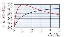
As explained in Maximum power transfer theorem § Maximizing power transfer versus power efficiency, the efficiency η of delivering power to a purely restive load impedance of RL from a voltage source with a purely restive output impedance of RS is:
This efficiency can be increased using impedance bridging, by decreasing RS and/or by increasing RL.
However, to instead transfer the maximum power from the source to the load, impedance matching should be used, according to the maximum power transfer theorem.
See also
References
- ↑ Eargle, John; Foreman, Chris (2002-01-01). Audio Engineering for Sound Reinforcement. Hal Leonard Corporation. ISBN 9780634043550.
In all modern usage the microphone looks into an impedance in the 2000 ohm range or higher, and this represents what is called a bridging load, one which is effectively an open circuit load for the microphone.
- ↑ Davis, Gary D.; Jones, Ralph (1989-01-01). The Sound Reinforcement Handbook. Hal Leonard Corporation. ISBN 9780881889000.
A circuit where the input termination impedance is a minimum of some 10 times the source impedance of the output driving that input is said to be a bridging input
- ↑ Holman, Tomlinson (2012-11-12). Sound for Film and Television. Taylor & Francis. ISBN 9781136046094.
In the case of bridging systems, we say the source impedance is low and the load impedances are high
- 1 2 3 4 5 Hess, Richard (1980). "Voltage Transmission for Audio Systems". www.richardhess.com. Archived from the original on 2020-02-20. Retrieved 2022-06-16.
- 1 2 Duncan, Ben (1985-04-01). "Interfacing The Line". Home & Studio Recording (Apr 1985): 56–58. Archived from the original on 2021-06-14.
- ↑ Duncan, Ben (1984-08-01). "Mating Microphones". Home & Studio Recording (Aug 1984): 46–47. Archived from the original on 2020-09-18.