Introduction

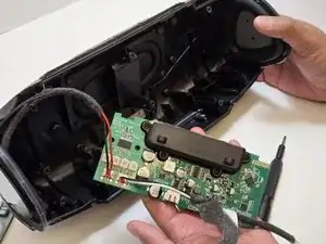
The W-King X10 Motherboard houses all of the electronic components that control the functions of the X10. These range from the Bluetooth Module chip to the onboard amplifiers for the speakers to the power circuit components that connect the battery to the other components.

The main way that the motherboard would become damaged would be by water getting into the casing of the X10. While the X10 is waterproof, damage to the casing could allow water into the internal components. This would cause a short circuit that could damage components across the motherboard.

If you need to replace the motherboard of your W-King X10 Bluetooth speaker, follow this guide.

Before you begin this repair, power off your speaker and disconnect it from the charging cable. The prerequisite guide to remove the speakers requires soldering. For detailed instructions, refer to the How to Solder and Desolder Connections guide.

  1. Ntkt2m3ybnVAsa3u
    • Make sure the X10 is powered off and disconnected from the charger before beginning the replacement.

    • Orient your W-King X10 so that the front is facing you.

    • The W-King logo will be facing you when the X10 is oriented correctly.

  2. raGHNpvDqiLX4tkN
    raGHNpvDqiLX4tkN
    1aaCbXVAXoH55CnG
    • Using a metal spudger, pry open the top points of the front-facing mesh guard.

    • The connection points are approximately in line with the strap clips on the central control panel.

    • You will hear an audible "pop" when the connection opens, and the top edge of the mesh guard will visibly separate from the X10.

  3. KDTuuPidqANNajcq
    KDTuuPidqANNajcq
    NHPXsbYARnqOVUCR
    xqGRnesAKSNZTYXV
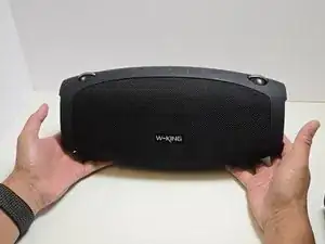
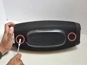
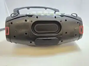
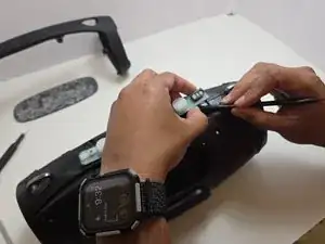
    • Lay the X10 on its back so that the bottom is facing you.

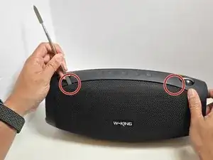
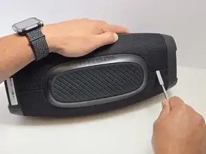
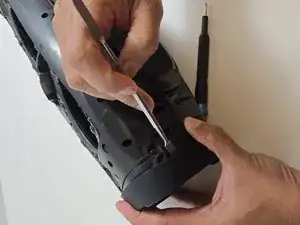
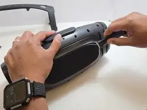
    • Using the metal spudger, separate the two connection points located on the left and right sides of the mesh panel as shown.

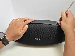
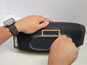
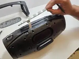
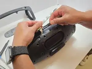
    • Separate the connection point in the center of the bottom section of the device.

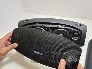
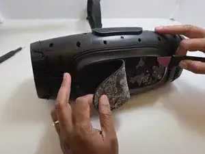
    • As before, all connection points should audibly 'pop' when disconnected, and the mesh panel will visibly separate from the body of the X10.

    • Take care not to accidentally reconnect the points you’ve already separated. Using opening picks to hold the connections open can be helpful as you complete this step.

  4. ww2LeRlUsE1lOffa
    • Remove the front and back mesh panels of the device.

  5. BajwN3SQNm2IcpkZ
    BajwN3SQNm2IcpkZ
    2WWaQCofBVTbbjZx
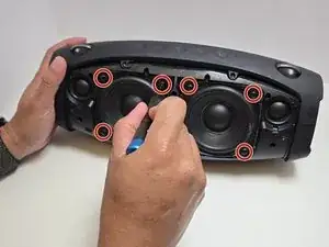
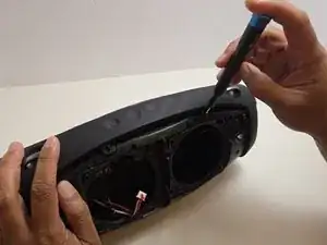
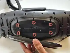
    • Use a Phillips #2 screwdriver to remove four 15.5 mm screws from the corners of each speaker.

  6. D6xVEejOQHWbvAOC
    D6xVEejOQHWbvAOC
    HyhrBdmwit6BIFwe
    • Gently pull the speaker straight out of the frame of the device.

    • If you tilt the speaker too far, it may catch on the frame, making it impossible to remove.

    • The speakers are connected to the board by cables, so avoid yanking or pulling on them forcefully.

  7. 5tMmIe3OOiMxfSru
    5tMmIe3OOiMxfSru
    V6AyHCHM4fWQRXDD
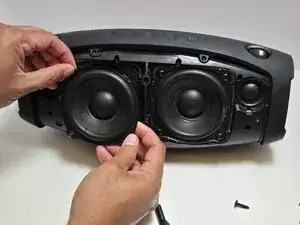
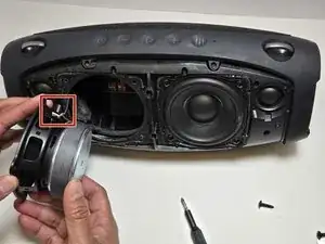
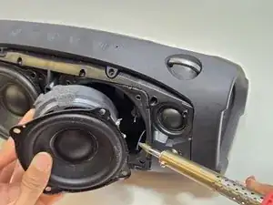
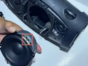
    • Use a soldering iron to disconnect the three wires connecting the speaker to the motherboard.

  8. jtbyhfqCY4lp6ygH
    jtbyhfqCY4lp6ygH
    qC1ibN2HDSFPKBoq
    Gm2iQXbTWQiDSBhF
    • Unscrew the top arm of the X10.

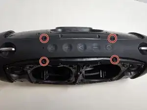
    • There are 4 7.5mm Phillips #0 screws at the center of the top arm.

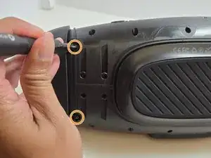
    • There are 2 7.5mm Phillips Head #0 screws at the base of each side of the arm.

  9. YLlx3bEoYV2IERMN
    YLlx3bEoYV2IERMN
    L55tmMiWHBvrdXbS
    • Use the metal spudger to dislodge the two clips on each side of the arm.

    • The two clips are at the front and back sides of the arm.

    • Remove the arm but pulling apart the two sides of the arm away from the casing and lifting the arm free from the casing.

    • All 4 clips must be dislodged in order to free the arm. Be careful not to accidentally reconnect one or more as you dislodge the others.

    • Removing the arm takes moderate force. The plastic is strong and should not break, but be careful with yourself and your X10.

  10. w1AuPTbHOPqDHVmX
    w1AuPTbHOPqDHVmX
    K1bbi5N3eYB5EpDV
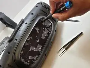
    • Remove the rubber foot at the bottom of the X10.

    • Use the Jimmy to separate the glue that holds the foot on to the casing.

    • Be gentle so as not to damage the soft rubber foot.

    • Peel away the rubber foot to expose the bottom panel of the casing.

  11. 4BJxBALrCWMQPYXw
    4BJxBALrCWMQPYXw
    HSyXjBUBKOpuQEf1
    J4jpKOdhE5HleQFr
    • Remove the Control Panel from the top of the X10 by using the plastic spudger to separate the glue that attaches it to the casing.

    • There will be limited slack on the panel until you disconnect the ribbon cable. Be careful to not overexert the cable by keeping the panel close to the casing until you have disconnected the cable.

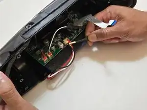
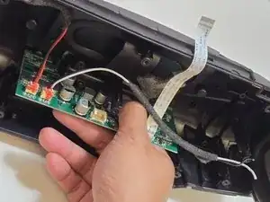
    • Using a pair of tweezers, gently pry the ribbon cable that connects the control panel to the motherboard.

  12. JTYAKI5rVwRlllnh
    JTYAKI5rVwRlllnh
    53cbGKMnkeRrDNxW
    • Use a Phillips #0 screwdriver to remove the six 7.5 mm screws connecting the bottom panel.

  13. KcYnRsQHgAReYYTc
    KcYnRsQHgAReYYTc
    wLZjhCDw5wXY2lOv
    TAulnDjS1AIyxkPU
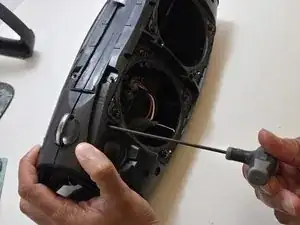
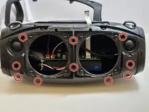
    • Use a 2.5 millimeter hex key to remove the ten 17.5 mm screws that connect the two halves of the X10 casing.

    • Several of these hex screws are in deep, narrow holes in the casing. We recommend using a full-length hex key rather than a hex bit at the end of a driver.

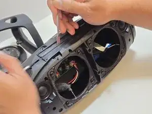
    • Separate the two halves of the casing using the metal spudger to pry apart the 10 connection arms that form the structure of the casing.

    • If this is the first time opening the casing of this X10, there will be glue around the seam of the casing. Use the spudger to split the glue to loosen the seam.

  14. GpdCat2nsDmLseII
    GpdCat2nsDmLseII
    jMj4HLLO6fuEBCWy
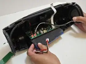
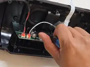
    • Use tweezers to disconnect the push-in wire connection between the battery and the motherboard.

    • Batteries connected to a circuit pose a risk of electrical shock. Use ESD-safe tools when handling electronics.

    • Remove the battery.

  15. Zpi5xGFnBBGyJ1It
    Zpi5xGFnBBGyJ1It
    3G1WmFD5M2Pi1KLp
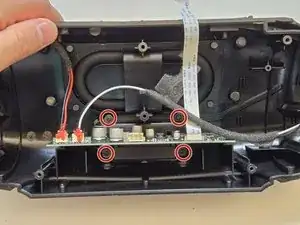
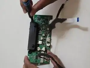
    • Use a Phillips #0 screwdriver to remove the four 7.5 mm screws connecting the casing motherboard to the case.

  16. UlxCSQCVaVWalkmy
    UlxCSQCVaVWalkmy
    tj1y1Uc3C6eCQJdx
    • Remove the motherboard from the X10 by pulling it straight out of the case.

    • To prevent damage to the motherboard, grip the plastic case attachment rather than the motherboard itself.

  17. TuffddHj1bjVHMtA
    TuffddHj1bjVHMtA
    QKUM3MHeDCPUEDhP
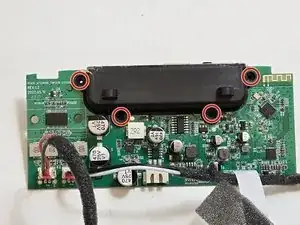
    • Use a Phillips #0 screwdriver to remove the four 11.5 mm screws connecting the black attachment to the motherboard.

Conclusion

To reassemble your device, follow these instructions in reverse order. Take your e-waste to an R2 or e-Stewards certified recycler.

Christian Diaz

Member since: 12/09/24

385 Reputation

0 comments