Introduction
If your W-King X10 has been functioning normally, but you are unable to charge the battery, you may have a problem with your charging port. When plugged in, the LED indicators at the top of the X10 should light up and blink white to indicate a charging battery and the level that the battery is charged.
After following our troubleshooting guide for potential quick-fixes, consider replacing the charging port itself by following this replacement guide.
Before you begin this repair, power off your speaker and disconnect it from the charging cable.
The prerequisite guide to remove the speakers requires soldering. For detailed instructions, refer to the How to Solder and Desolder Connections guide.
-
-
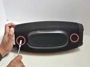
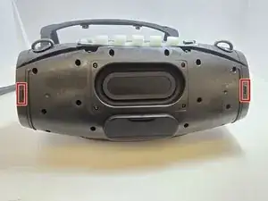
Lay the X10 on its back so that the bottom is facing you.
-
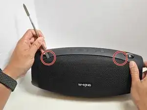
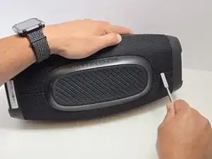
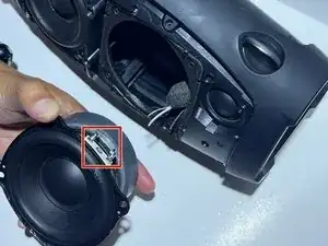
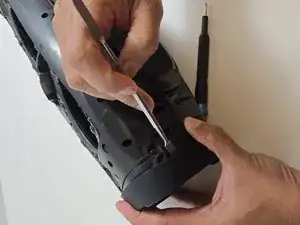
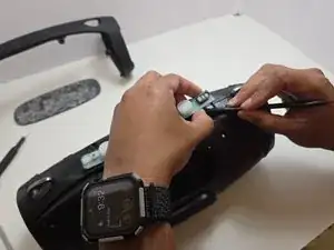
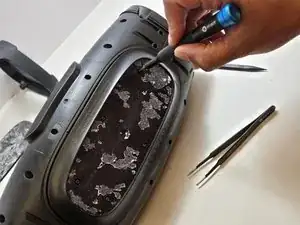
Using the metal spudger, separate the two connection points located on the left and right sides of the mesh panel as shown.
-
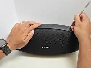
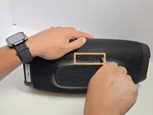
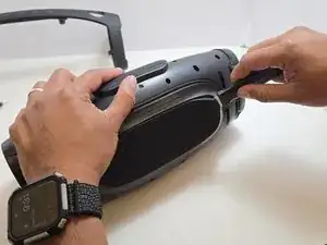
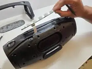
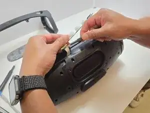
Separate the connection point in the center of the bottom section of the device.
-
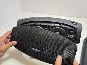
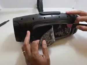
As before, all connection points should audibly 'pop' when disconnected, and the mesh panel will visibly separate from the body of the X10.
-
-
-
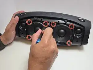
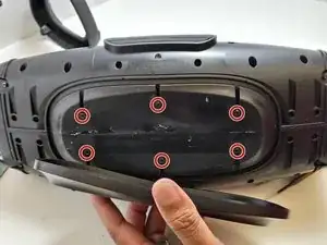
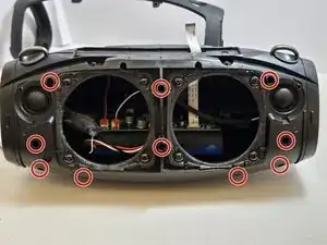
Use a Phillips #2 screwdriver to remove four 15.5 mm screws from the corners of each speaker.
-
-
-
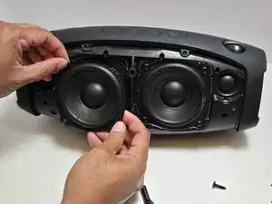
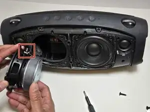
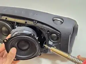
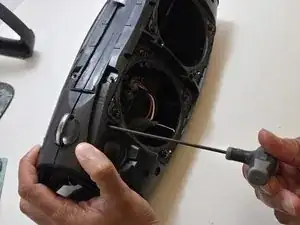
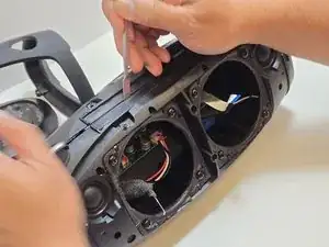
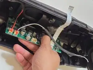
Use a soldering iron to disconnect the three wires connecting the speaker to the motherboard.
-
-
-
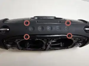
Unscrew the top arm of the X10.
-
There are 4 7.5mm Phillips #0 screws at the center of the top arm.
-
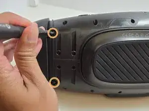
There are 2 7.5mm Phillips Head #0 screws at the base of each side of the arm.
-
-
-
Use the metal spudger to dislodge the two clips on each side of the arm.
-
The two clips are at the front and back sides of the arm.
-
Remove the arm but pulling apart the two sides of the arm away from the casing and lifting the arm free from the casing.
-
-
-
Remove the rubber foot at the bottom of the X10.
-
Use the Jimmy to separate the glue that holds the foot on to the casing.
-
Peel away the rubber foot to expose the bottom panel of the casing.
-
-
-
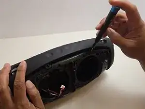
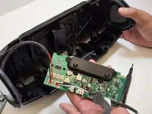
Remove the Control Panel from the top of the X10 by using the plastic spudger to separate the glue that attaches it to the casing.
-
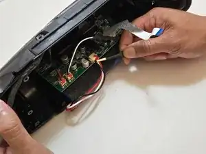
Using a pair of tweezers, gently pry the ribbon cable that connects the control panel to the motherboard.
-
-
-
Use a 2.5 millimeter hex key to remove the ten 17.5 mm screws that connect the two halves of the X10 casing.
-
Separate the two halves of the casing using the metal spudger to pry apart the 10 connection arms that form the structure of the casing.
-
-
-
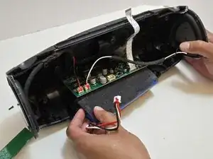
Use tweezers to disconnect the push-in wire connection between the battery and the motherboard.
-
Remove the battery.
-
-
-
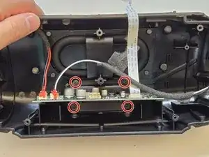
Use a Phillips #0 screwdriver to remove the four 7.5 mm screws connecting the casing motherboard to the case.
-
-
-
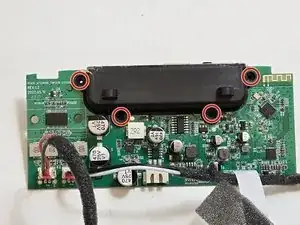
Use a Phillips #0 screwdriver to remove the four 11.5 mm screws connecting the black attachment to the motherboard.
-
-
-
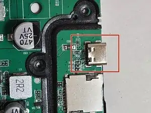
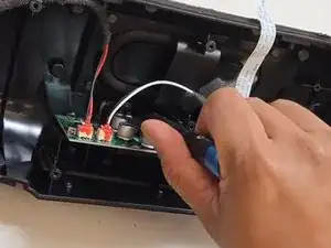
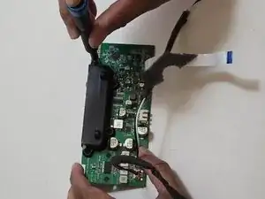
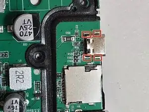
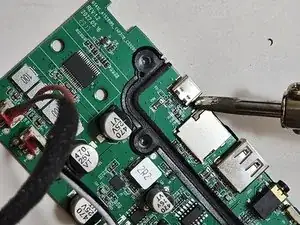
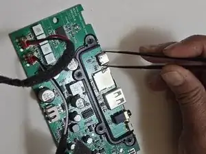
Use a soldering iron to desolder the four connection points attaching the charging port to the motherboard.
-

To reassemble your device, follow these instructions in reverse order. Take your e-waste to an R2 or e-Stewards certified recycler.