Introduction

Use this guide to replace the right touchpad on your Steam Deck OLED. The touchpad itself is part of a larger module, including haptics, and needs to be replaced as one unit.

Although the procedure is similar, follow this guide to replace the left touchpad.

Remember to follow general electrostatic discharge (ESD) safety procedures while repairing your device.

These steps only describe how to physically remove and replace your console’s touchpad. You may need additional software tools and calibration procedures to get the replacement touchpad to function as intended.

  1. wg1CPbiBgYbiTVlf
    wg1CPbiBgYbiTVlf
    nJjXUM3KksnJHIgN
    mLdVpQ6WWvINGWuE
    • Turn on your Steam Deck and allow the battery to discharge below 25% before starting your repairs, as a charged lithium-ion polymer battery can be dangerous if accidentally punctured.

    • As an extra precaution, Valve recommends putting your Steam Deck into battery storage mode within the BIOS before starting any internal repairs. Read how to do that here.

    • Power down your Steam Deck and unplug any cables.

    • If you have a microSD card installed, make sure to remove it before opening the Steam Deck. If you attempt to remove the back cover with it still installed, it could snap right in half.

    • During your repair, it can be helpful at times to lay the Steam Deck face-down in its case to protect the thumbsticks and prevent wobble.

  2. CU2nvWsgJGWI2Rut
    CU2nvWsgJGWI2Rut
    HUaIpoLKT3gGOD53
    • Use a T6 Torx driver to remove the eight 5.8 mm‑long screws securing the back cover.

    • Throughout this repair, keep track of each screw and make sure it goes back exactly where it came from.

  3. rEBEVxNkrDU5dsek
    rEBEVxNkrDU5dsek
    rIRRhvkBKVWODhWI
    A4aS52mtPxxkwit5
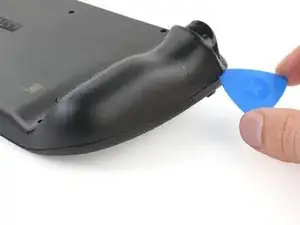
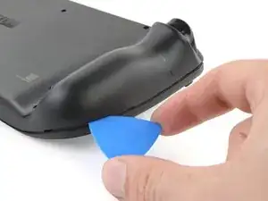
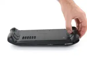
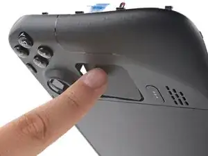
    • Insert an opening pick at an upward angle between the back cover and the front shell near one of the triggers.

    • If you can't insert your pick here, try along the top or bottom edges of the Steam Deck OLED before sliding it toward the handle.

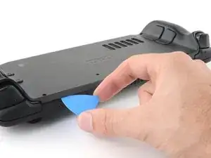
    • Slide your pick along the edge of the handle to release the clips securing it to the front shell.

  4. yYcl1PRUGUuYu2AV
    yYcl1PRUGUuYu2AV
    Z61KAZVNuuuFxgBL
    5ji5HRJa5qu1niLI
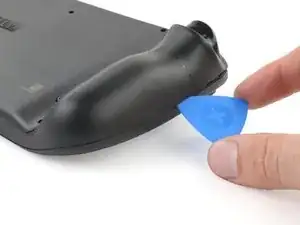
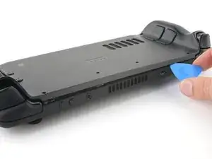
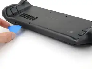
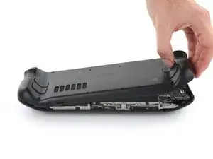
    • Reinsert your pick and slide it along the top and bottom edges until the back cover feels loose.

  5. 3hO2o6jhWtTFtqUB
    3hO2o6jhWtTFtqUB
    HZa1Pau2KaJcrM1I
    2pXBrjoLgvKGSFGx
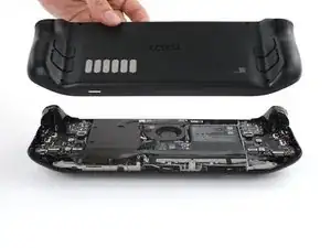
    • Grip the unclipped handle and pull it away from the front shell to release the remaining clips.

    • Remove the back cover.

  6. OKJYYpHQNvn4X1nk
    OKJYYpHQNvn4X1nk
    GaA5rrvDLfGCHRBc
    d6WmlRapenltwItT
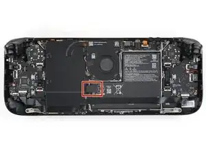
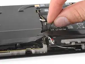
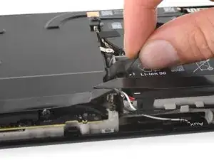
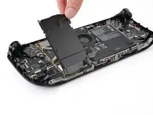
    • Grip the battery cable pull tab, located to the left of the battery.

    • Firmly pull the battery cable straight away from the motherboard shield (toward the battery) to disconnect it.

    • This bundled cable is fairly stiff. If you're having trouble, re-grip the pull tab close to the head of the connector and gently walk it side-to-side as you pull.

    • If the cable pull-tab feels fragile or rips during this process, remove the motherboard shield and disconnect the cable using a spudger.

    • When the battery cable comes free, it might push up on the motherboard shield. Don't worry, as this won't damage anything.

    The pull tab can come off revealing the wires. The instructions should be updated to reflect that catch.

    Khurram Tariq -

    Hallo,

    gibt es die Abschirmung auch als Ersatzteil irgendwo zu kaufen?

    Danke

    Yannick B. -

    Bad step. Remove the shield plate from the next step first then safely disconnect the battery. Using this type of pull force here made the pull tab peel away exposing the wires.

    Jaspal Goshal -

  7. Y2dKx1uklHVSgHct
    Y2dKx1uklHVSgHct
    YfYdFfjbm6ftyKGo
    • During disassembly, skip the next three steps.

    • During reassembly:

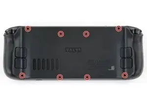
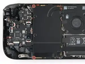
    • Reinstall the two 3.8 mm‑long screws to secure the motherboard shield.

    • Reconnect the interconnect cable ZIF connector.

  8. NPOSGMuDh4R1TBPD
    NPOSGMuDh4R1TBPD
    5AjsBfuQL1MnMiOy
    cCwJITNQcAn1kQw6
    • During reassembly:

    • Use the flat end of a spudger to slide the battery connector into its socket on the motherboard.

  9. VFpxUmTfIGIlRmnr
    VFpxUmTfIGIlRmnr
    BHXO1C63DbO2xvVe
    DnV2d2OCHTvhyFfn
    • During reassembly, follow this step and the above three steps to reconnect the battery.

    • Use your T6 Torx driver to remove the two 3.8 mm‑long screws securing the motherboard shield.

    • Lift the top edge of the motherboard shield up and flip it over the bottom edge of the frame, away from the motherboard.

    • Be careful not to crease or strain the cable.

  10. XpagOU5LKi1flVnI
    XpagOU5LKi1flVnI
    VlwoMcX5CacObH6b
    CwgwW1yoAOc6PeBT
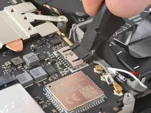
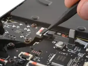
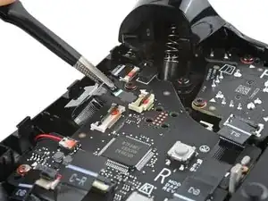
    • Use the point of a spudger to flip up the small locking flap on the right thumbstick ZIF connector.

    • The pull tab on this connector may be labeled TS.

    • Use tweezers or your fingers to grip the cable's pull tab and slide the connector straight out of its socket to disconnect it.

  11. yfpkeTabjHZY2kms
    yfpkeTabjHZY2kms
    ZDlPWZFcXl6XHphv
    kcdJNr3WUUTL5fND
    • Use a spudger to flip up the small white locking flap on the right button board interconnect cable ZIF connector.

    • The pull tab on this connector may be labeled C‑R.

    • Use tweezers or your fingers to grip the cable's pull tab and slide it straight out of its socket to disconnect it.

    • During reassembly, don't reconnect this cable yet. You'll reconnect it later.

  12. Qg1WFxGkTIPsWSBy
    Qg1WFxGkTIPsWSBy
    TtwOTmDJNyPjuFJj
    ivkESZwsTC5jlmm1
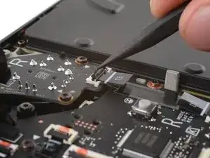
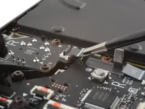
    • Flip up the small black locking flap on the right thumbstick cable ZIF connector.

    • The pull tabs on the remaining ZIF connectors in this procedure may be labeled DB.

    • Slide the connector straight out of its socket to disconnect it.

  13. RM6Rbya4vMQFXCmh
    RM6Rbya4vMQFXCmh
    bLCektHanXlfyKnm
    SSxD1qaIZ1QDBkAK
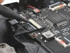
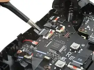
    • Flip up the small locking flap on the button board cable ZIF connector, located in the bottom left corner.

    • Slide the connector straight out of its socket to disconnect it.

  14. MMtxyfOIogRU41Tu
    MMtxyfOIogRU41Tu
    Rn2aowjCDLlaba6s
    3BySZCopNSfPHxi1
    • Repeat the ZIF cable disconnection procedure for the remaining three ZIF connectors:

    • The touchpad cable

    • The touchpad board cable

    • You may need to lift this cable as you pull to free its arms.

    • The action buttons and menu button cable

  15. VLr3NfIWbLoQ3lRE
    VLr3NfIWbLoQ3lRE
    F2YYQpYw3lF14bc6
    kKXJStoqmJPJCZbK
    • If you aren't replacing your button board, you can leave this cable connected and lay the board over the left side of the frame after you've removed the screws.

    • Be careful when disconnecting the haptics, as the cables and connector are very delicate. Pry only on the base of the white connector, and not on the cables or socket.

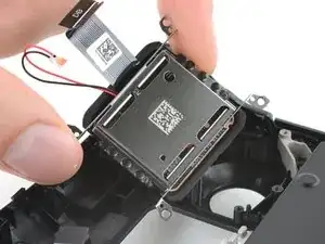
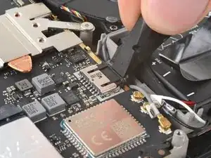
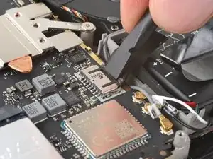
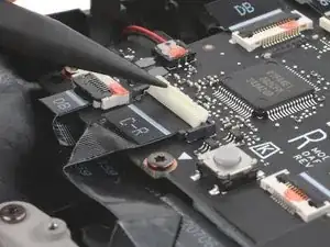
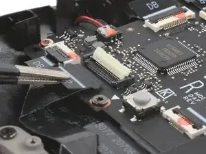
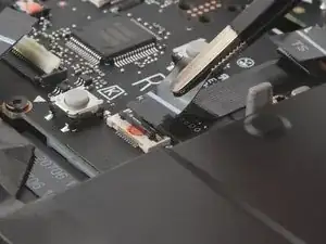
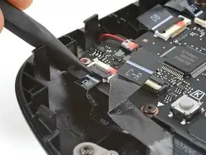
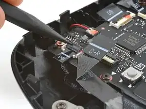
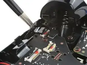
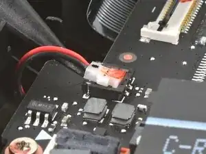
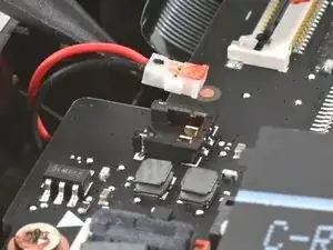
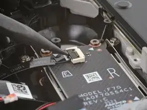
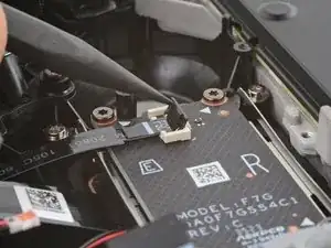
    • Insert the point of your spudger under the neck of the haptics cable connector.

    • Gently pry up to disconnect it.

  16. Z3oH6vDeCHPunVHT
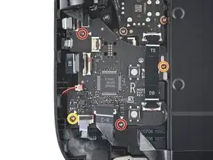
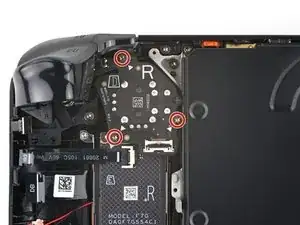
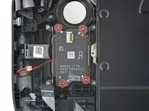
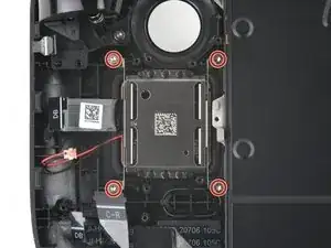
    • Use your T6 Torx driver to remove the four screws securing the right button board:

    • Two 5.9 mm‑long screws

    • One 3.8 mm‑long screw

    • One 4.9 mm‑long screw

  17. aCOCXccOTCh6p1jF
    aCOCXccOTCh6p1jF
    SQHogKmZRMVTNxXh
    HfC2MPQdkoBgN5Hl
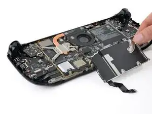
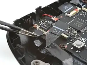
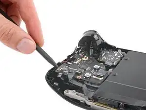
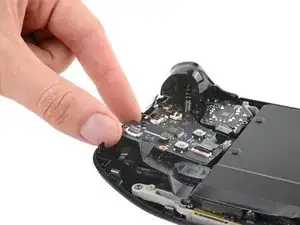
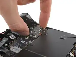
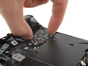
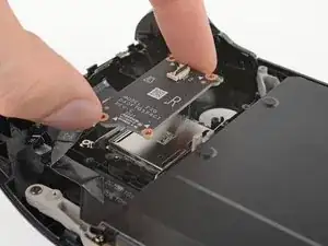
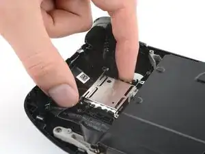
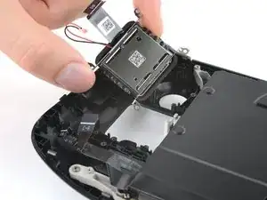
    • Insert the point of your spudger between the bottom left corner of the button board and the frame.

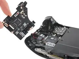
    • Pry up until you can grab the button board with your fingers.

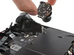
    • Remove the button board.

    • During reassembly, make sure none of the six cables become trapped underneath the button board as you lay it into place.

  18. QZyDqKjglMBudouQ
    QZyDqKjglMBudouQ
    IVWJvlrhVnUP2KYP
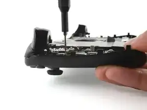
    • Use your T6 Torx driver to remove the three 5.9 mm‑long screws securing the right thumbstick.

    • During reassembly, hold the Steam Deck OLED off your work surface so it doesn't rest on your thumbstick as you tighten the screws.

  19. pEGdARwGyDXDU1Ui
    pEGdARwGyDXDU1Ui
    imPEvS2SXXJSMDkR
    GCZwTarI1p2bDO1B
    • Grip the edges of the thumbstick board and rotate it clockwise to clear the trigger.

    • Remove the thumbstick.

  20. BkrxOX1U5NfilwPU
    BkrxOX1U5NfilwPU
    tsYGFAWY1QDQQqmC
    • Use tweezers to remove the quick access button membrane.

  21. TC1Lo6KnHQKbfd3d
    TC1Lo6KnHQKbfd3d
    ACW1goTQPIsJ1sbf
    pDVLJGsR3m2yYA26
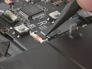
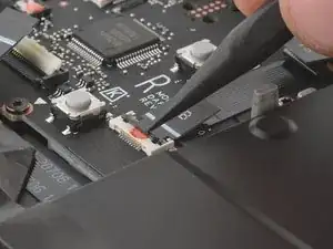
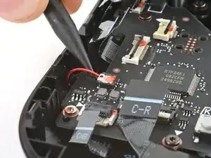
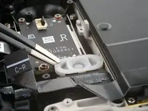
    • Flip up the small locking flap on the right touchpad board ZIF connector.

    • Lift the connector until its arms are free of the socket and slide it straight out to disconnect it.

  22. 45xfDL1oheY1Flnb
    • Use your T6 Torx driver to remove the four 5 mm‑long screws securing the touchpad board.

  23. 2PGReQSThKNQVC1H
    2PGReQSThKNQVC1H
    GGihwM1fEaJqhJpk
    • Use your fingers to remove the touchpad board.

  24. btHLCFOEjNPYXDXp
    • Use your T6 Torx driver to remove the four 6 mm‑long screws securing the touchpad.

  25. wQECsiIWgNH4JwuT
    wQECsiIWgNH4JwuT
    uBhhlLQGDHH1JQjn
    Jl3Hf4UQiaYShRBB
    • Remove the touchpad.

    • If you're having trouble removing the touchpad, lift the edge of the Steam Deck OLED and push the touchpad through from the front.

Conclusion

To reassemble your device, follow these instructions in reverse order.

Take your e-waste to an R2 or e-Stewards certified recycler.

Repair didn’t go as planned? Try some basic troubleshooting, or ask our Steam Deck OLED answers community for help.

Clay Eickemeyer

Member since: 19/09/22

77552 Reputation

One comment

Where can the touchpads be bought from? Can't find them anywhere...

KirbyDaDragon -