
Introduction
Use this guide to replace the battery in your Microsoft Surface Laptop 4 (15-inch).
If your battery is swollen, take appropriate precautions.
You'll need replacement adhesive for the battery to complete this repair. Strong double-sided tape like Tesa 61395 is recommended.
Some photos in this guide are from a different model and may contain slight visual discrepancies, but they won't affect the guide procedure.
-
-
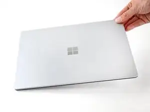
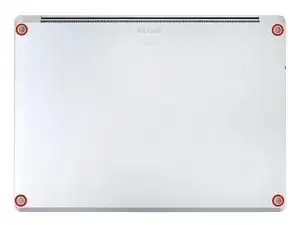
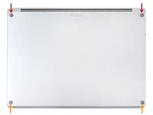
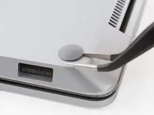
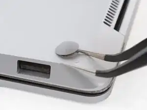
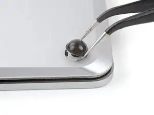
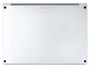
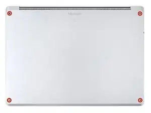
Close the screen and lay your laptop down with the rear case facing up to access the four rubber feet.
-
-
-
The back feet recesses are closest to the back edge of the laptop.
-
The front feet recesses are closest to the front edge of the laptop.
-
-
-
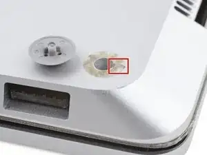
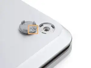
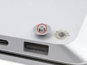
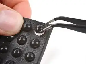
The rear feet have a single center clip.
-
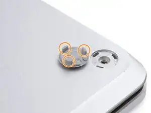
The front feet have three clips and can only be reinserted one way.
-
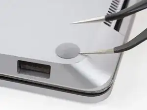
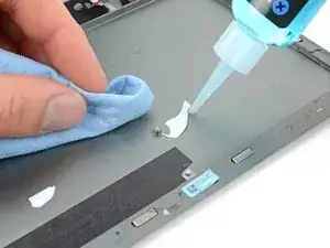
If the existing feet no longer adhere to the frame, remove the old adhesive and apply a small amount of Tesa Tape where the old adhesive was.
-
-
-
Peel a pad away from its backing.
-
Align the pad over a foot cavity and press down to secure it.
-
-
-
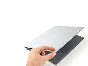
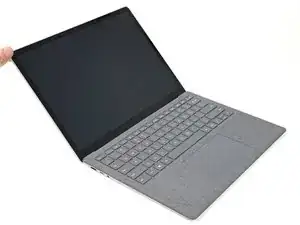
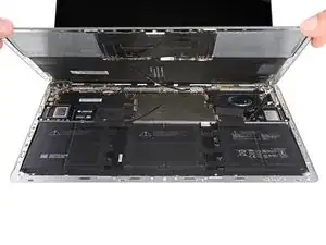
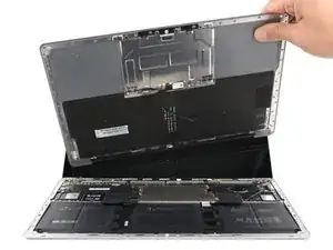
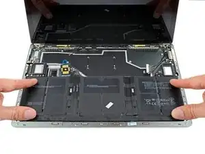
Grip the top edge of the upper case above the keyboard and lift straight up to release it.
-
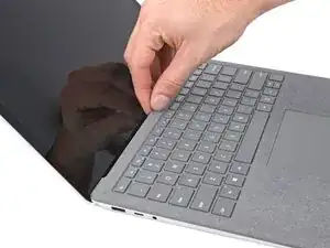
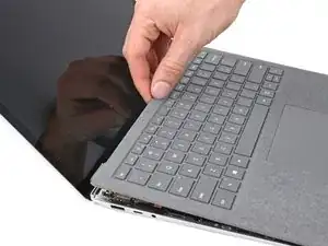
Lift the bottom edge of the upper case up and away from the laptop, taking care to not strain the ribbon cable underneath.
-
-
-
Insert the pointed end of a spudger under one edge of the magnet connector and pry up to disconnect it.
-
-
-
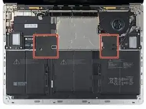
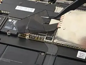
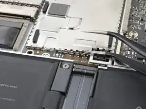
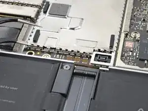
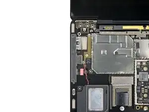
Remove the two pieces of black tape covering the bottom left and bottom right corners of the motherboard.
-
-
-
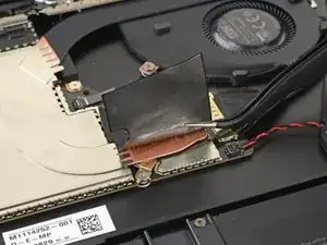
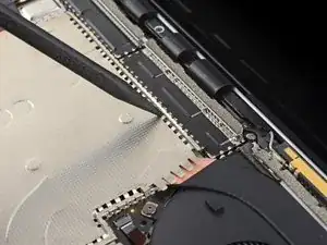
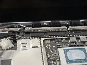
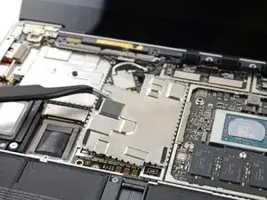
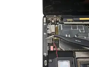
Insert the pointed end of a spudger in one of the gaps on the top edge of the heatsink shield.
-
Gently pry up to release the clips securing the shield.
-
Repeat this process along the right edge.
-
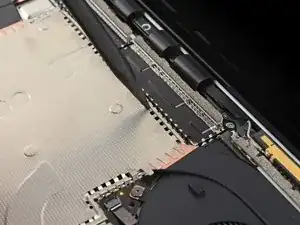
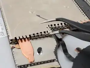
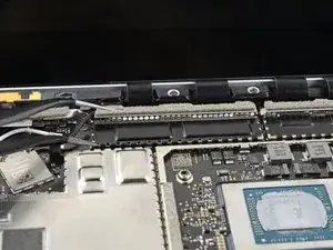
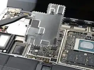
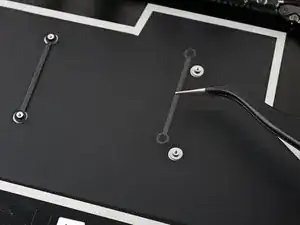
Insert one arm of your tweezers under the bottom right edge of the heatsink shield.
-
Gently pry up to release the remaining clips.
-
-
-
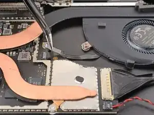
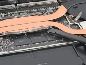
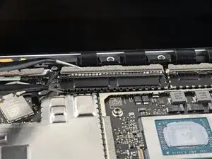
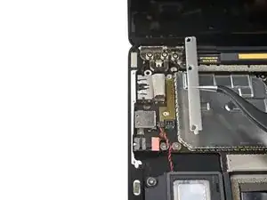
Use the pointed end of a spudger to flip up the locking flap on the fan cable ZIF connector.
-
Grip the fan cable pull-tab with tweezers and pull the cable straight out of the connector.
-
-
-
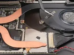
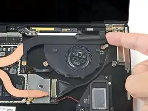
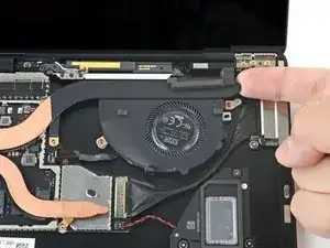
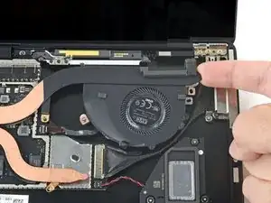
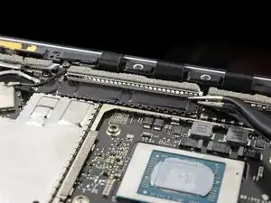
Use tweezers or your fingers to peel the fan cable from the frame and separate its adhesive.
-
-
-
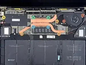
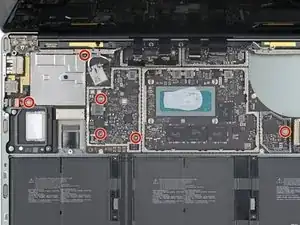
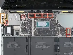
Use a T3 Torx driver to remove the ten screws securing the heatsink:
-
Two 2.5 mm screws
-
Three 2.0 mm screws
-
One 3.0 mm screw
-
Two 4.1 mm screws
-
Two 3.4 mm screws
-
-
-
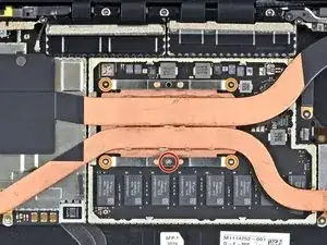
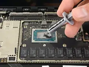
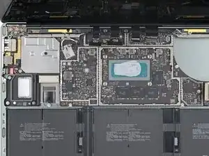
Align the heatsink with the centering peg on the motherboard.
-
Tighten the four CPU tension screws in an “X” pattern. For example: top left, bottom right, top right, bottom left.
-
-
-
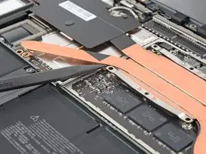
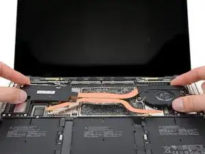
Insert your spudger under the left heat pipe.
-
Pry up to release the left section of the heatsink.
-
Repeat this procedure for the right heat pipe and the CPU screw mounts until the heatsink is completely separated from the motherboard.
-
-
-
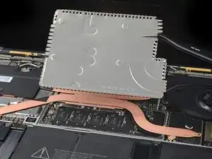
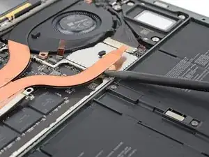
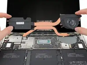
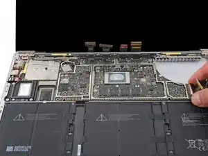
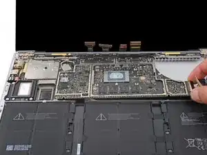
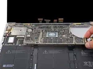
Use your finger to lift the right edge of the heatsink up and over the alignment peg near the right side of the fan.
-
Lightly pull the right edge of the heatsink away from the screen to release it from its recess in the frame.
-
-
-
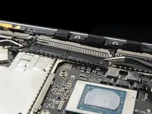
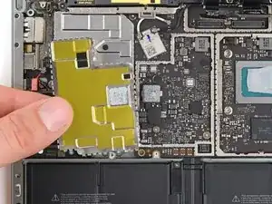
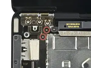
Insert one arm of your tweezers under the corner of the left display cable shield.
-
Gently pry up to release the clips securing the shield.
-
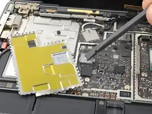
Repeat this process around the perimeter of the shield until you can remove it.
-
-
-
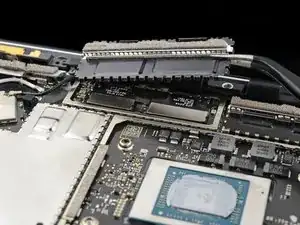
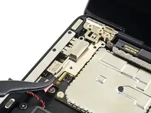
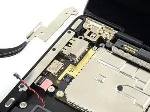
Pull the left display cable shield way from the screen to free it from its recess.
-
Remove the shield.
-
-
-
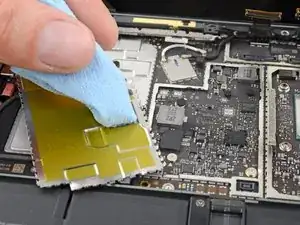
Insert one arm of your tweezers under the corner of the left touchpad shield.
-
Gently pry up to release the clips securing the shield.
-
Repeat this process around the perimeter of the shield until you can remove it.
-
-
-
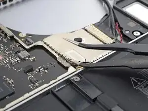
Insert one arm of your tweezers under the corner of the right motherboard shield and pry around its perimeter up to release the clips.
-
Remove the right motherboard shield.
-
-
-
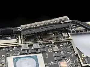
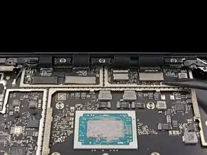
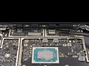
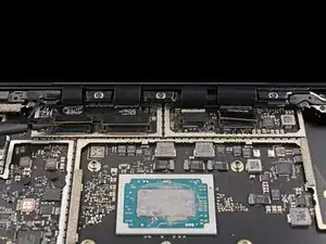
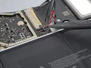
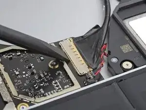
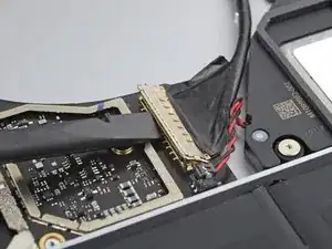
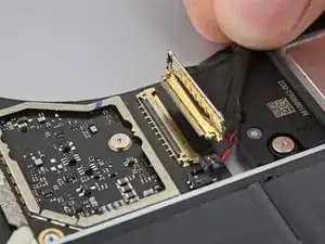
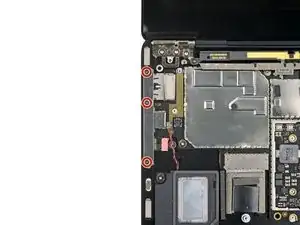
Use the flat end of a spudger to pry up and disconnect all four display cable press connectors.
-
-
-
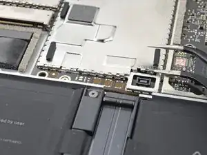
Use the pointed end of a spudger to lift and disconnect the right speaker wire from its connector on the motherboard.
-
-
-
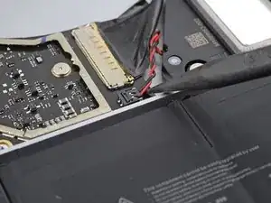
Use the flat end of a spudger to flip open the locking arm on the Surface Connect port connector.
-
Grip the Surface Connect port cable and pull it straight out of its socket.
-
-
-
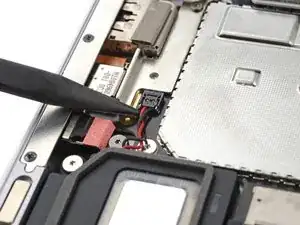
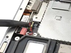
Use the pointed end of a spudger to lift and disconnect the left speaker wire from its connector near the left ports.
-
-
-
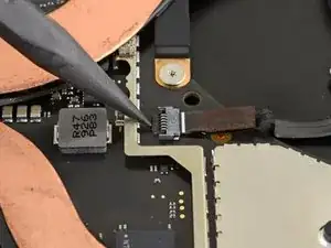
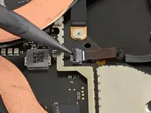
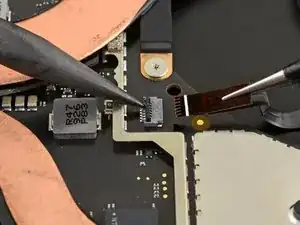
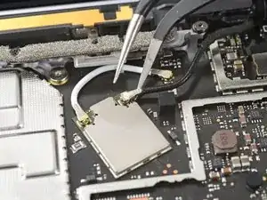
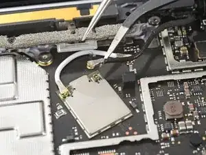
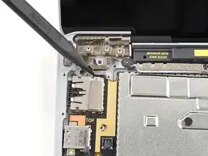
Slide one arm of your tweezers under the black antenna connector, as close to the head as possible.
-
Lift straight up to disconnect the cable.
-
-
-
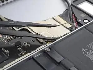
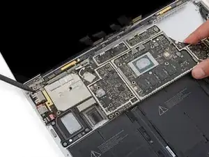
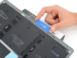
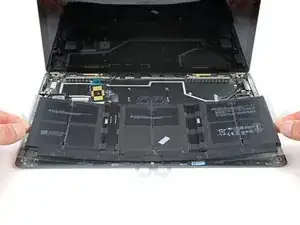
Lift the right edge of the motherboard slightly over the battery.
-
Hold the motherboard in place while you follow the step to free the left edge.
-
-
-
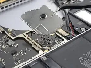
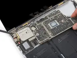
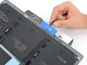
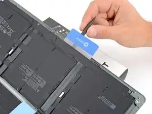
Insert the tip of a spudger against the tab in the upper left corner of the motherboard. Wedge the spudger between the frame and the screen hinge.
-
Pry up on the tab with your spudger while you lift the right edge of the motherboard toward the front of the laptop.
-
-
-
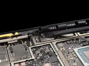
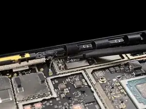
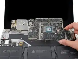
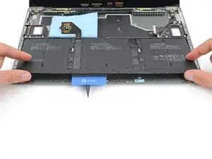
Remove the motherboard.
-
Make sure none of the eight cables get trapped underneath.
-
Position the left ports in their recess before sliding the motherboard into place.
-
-
-
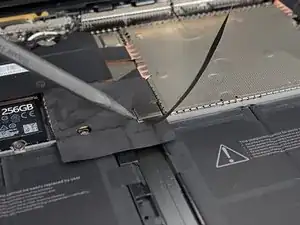
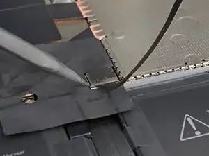
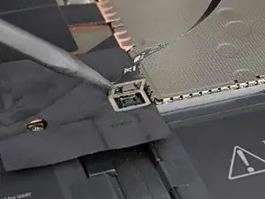
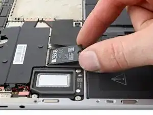
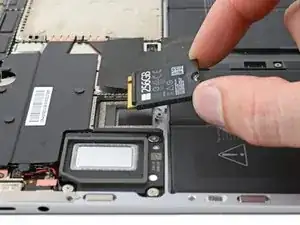
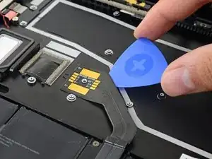
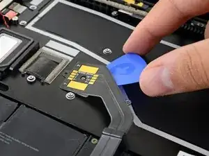
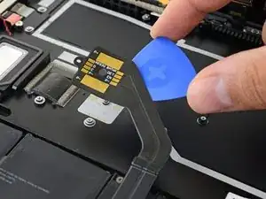
Slide an opening pick under the battery cable and pry up to separate it from the frame.
-
If your battery cable has a plastic liner, remove it. Otherwise, apply double-sided tape to the underside of the cable.
-
Line up the cable with its screw post and alignment peg, and press down to secure the cable to the frame.
-
-
-
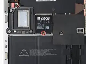
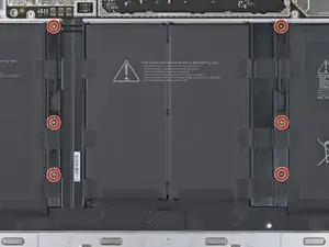
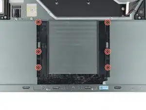
Use a T3 Torx driver to remove the six 2.7 mm screws securing the battery spacers to the frame.
-
-
-
Wear eye protection when handling and applying the adhesive remover.
-
Do not wear contact lenses without eye protection.
-
Wear protective gloves to prevent skin irritation.
-
-
-
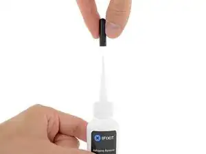
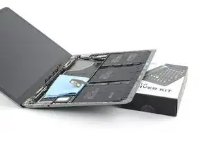
Hold your bottle of adhesive remover right side up and pull off the black rubber stopper.
-
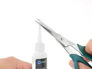
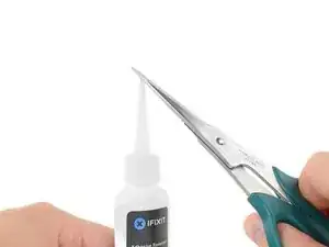
Use scissors to cut off the sealed tip of the applicator.
-
-
-
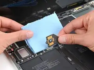
Place a paper towel under the battery contact cable to prevent excess adhesive remover from flowing through its cutout.
-
-
-
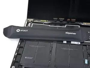
Prop up the front edge of your laptop slightly to allow the adhesive remover to flow under the battery.
-
-
-
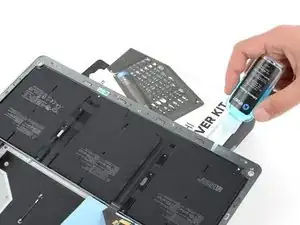
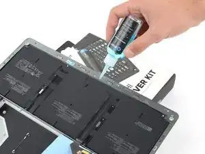
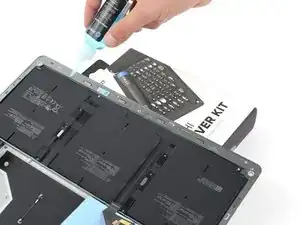
Apply a few drops of adhesive remover evenly under the elevated edge of the battery cells.
-
Wait two minutes for the adhesive to soften.
-
-
-
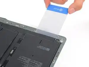
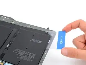
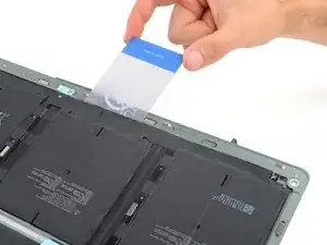
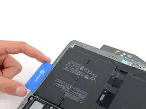
Insert a plastic card under the elevated edge of the left battery cell.
-
Slide the card under the battery to separate the adhesive securing it to the frame.
-
-
-
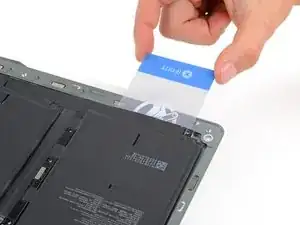
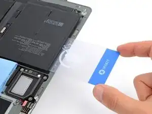
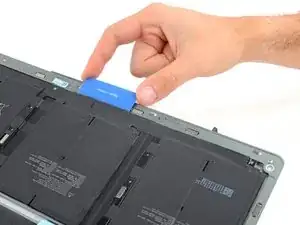
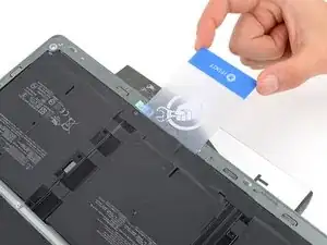
Slide your plastic card under the outer edge of the left battery cell to completely separate it from the frame.
-
-
-
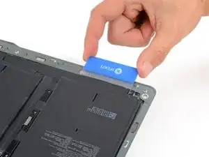
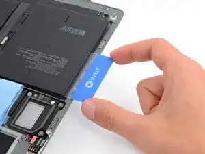
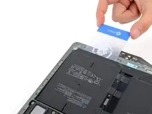
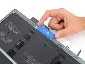
Remove your plastic card so it's only underneath the battery board.
-
Keep your card under the battery board and slide it to the middle cell.
-
Slide your card under the middle battery cell to separate the adhesive securing it to the frame.
-
-
-
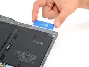
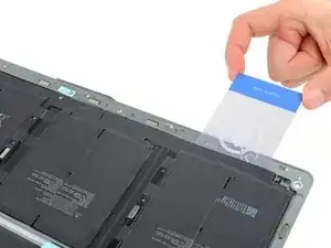
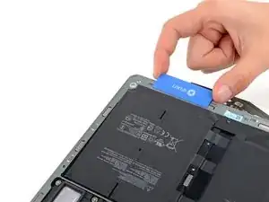
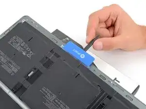
Slide your plastic card under the right battery spacer, on the inside edge of the screw posts in the frame.
-
Slide a spudger under the plastic card and gently lift to separate the adhesive securing the battery spacer to the frame.
-
-
-
Slide your plastic card again underneath the left battery spacer and pry it up with a spudger.
-
-
-
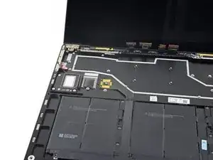
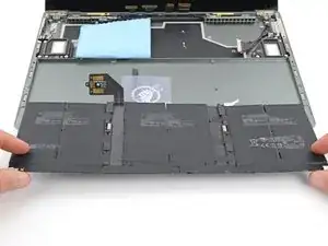
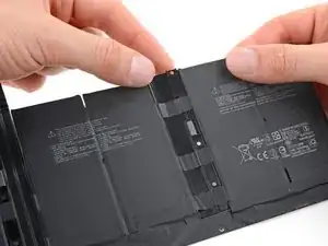
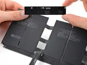
Remove the battery from its recess.
-
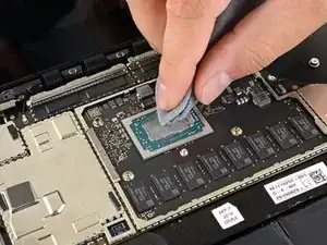
Use adhesive remover or highly-concentrated isopropyl alcohol (over 90%) to soften any residue on the frame.
-
Wipe the residue from the frame using a microfiber or lint-free cloth.
-
-
-
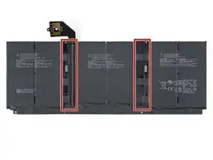
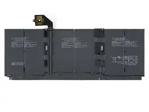
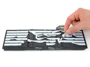
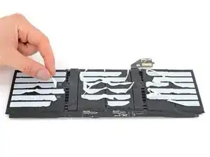
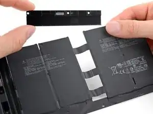
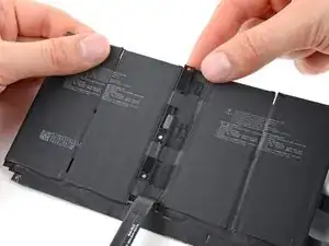
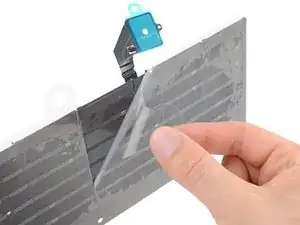
Flip your battery over and locate the spacers between the cell groups.
-
Use your fingers to peel away any adhesive strips from the battery spacers.
-
-
-
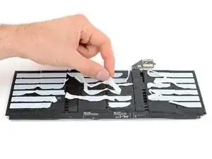
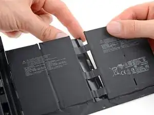
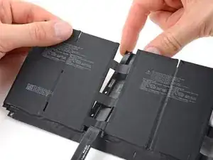
Hold up the battery cell groups on either side of the right spacer.
-
Peel the spacer from the strips of tape connecting the cell groups.
-
Remove the spacer.
-
-
-
Orient the battery spacers so their screw holes are on the outside.
-
Use your T3 Torx driver to install the six 2.7 mm screws into the spacers.
-
-
-
Orient your battery using the two alignment pegs and six screw posts in the frame.
-
If your new battery already has adhesive, peel off it's protective liners. If not, secure the battery with thin double-sided tape such as Tesa 61395.
-
Set the battery into place. Firmly press on the entire surface of each battery cell to secure it to the frame.
-


For optimal performance, calibrate your newly installed battery after completing this guide.
To reassemble your device, follow these instructions in reverse order, starting here.
Compare your new replacement part to the original part—you may need to transfer remaining components or remove adhesive backings from the new part before you install it.
Take your e-waste to an R2 or e-Stewards certified recycler.
Repair didn’t go as planned? Try some basic troubleshooting or check out our Answers community for help.
