Introduction

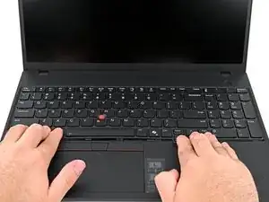
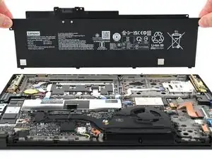
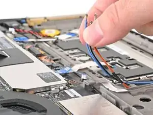
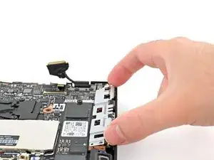
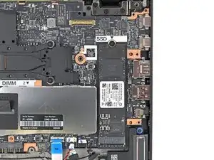
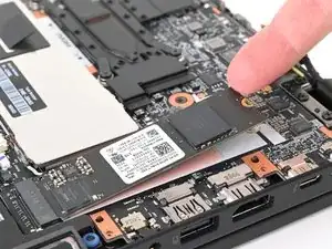
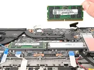
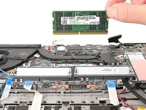
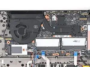
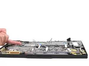
Follow this guide to replace the motherboard (aka system board) in your Lenovo ThinkPad T16 Gen 3 laptop.

This board contains the processor and the ports on the left side. If the ports on the right side of your T16 Gen 3 are malfunctioning, you may need to replace the I/O board.

  1. CY1FNfFHtHGNYF34
    CY1FNfFHtHGNYF34
    VfJ5QEBGFMlOTFEF
    gXQresPv2NbAxsyQ
    • For your safety, discharge your battery below 25% before disassembling your laptop. A charged battery may catch fire if damaged. If your battery is swollen, take appropriate precautions.

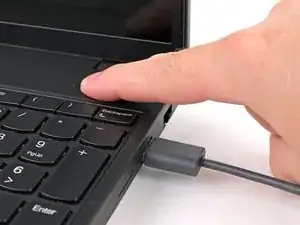
    • Completely shut down your laptop (don't just put it in sleep mode) and disconnect all cables.

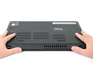
    • Flip the laptop upside-down, and rotate it so the screen hinge faces towards you.

  2. nQ2CwdrKNiB5hcay
    nQ2CwdrKNiB5hcay
    KWGeXyketj2CXit1
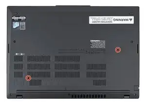
    • Use a Phillips screwdriver to fully loosen the two captive screws securing the keyboard to the laptop.

    • The two keyboard screws are labeled with a keyboard icon.

  3. kH6obxHXOPHPa1N5
    kH6obxHXOPHPa1N5
    n2g1PrTEDOLm5bZG
    cn6T6lEZJcRHZbmi
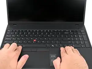
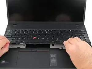
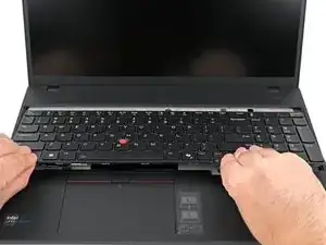
    • Place your fingers on the bottom edge of the keyboard.

    • Push the keyboard towards the screen until you can lift the bottom edge.

    • Lift the bottom edge of the keyboard slightly off your laptop.

    • Don't try to remove the keyboard yet—two ribbon cables still connect it to the laptop.

  4. HSCI4hfRFlcOPRGu
    HSCI4hfRFlcOPRGu
    jxriaWaLussBsvSw
    vCnPCJOfMTJbcEPH
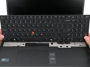
    • With the bottom edge lifted, pull the keyboard away from the screen until it's free from the chassis.

    • While disconnecting the cables in the next two steps, hold the keyboard upright or gently flip it over onto the trackpad. Be very careful not to strain the cables.

    • During reassembly, ensure both cables are laying completely flat to avoid bulging the keyboard or damaging components.

  5. JHFyvgCuESFoNat2
    JHFyvgCuESFoNat2
    SjNNEXnt3nILPiMo
    ASwrvlcoUxnKad2q
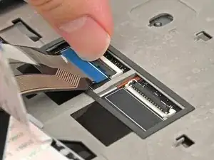
    • Use your fingernail or the flat end of a spudger to flip up the locking flap on the TrackPoint cable ZIF connector.

    • Use your fingers or tweezers to gently pull the cable out of its socket.

  6. CP1jjIdswR6UjAAt
    CP1jjIdswR6UjAAt
    hcdcqCOZNJxAaAyO
    JlDptowXCAoSVFon
    • Repeat the process to disconnect the keyboard cable.

  7. Ht5qDF1F4HeXvRmb
    • Remove the keyboard from your laptop.

  8. KDvJhEEAJYeQkFpr
    • Close your laptop, flip it upside-down, and rotate it so the screen hinge faces towards you.

  9. NbeUZSWVdADFi5Di
    NbeUZSWVdADFi5Di
    ymBjnZObejVL3coI
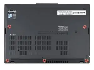
    • Use a Phillips screwdriver to fully loosen the five remaining captive screws securing the base cover.

  10. qVQxCLKO2IocpZ1W
    qVQxCLKO2IocpZ1W
    vKneKeGoTCc3K1vZ
    TiJF6whcX2xRelEe
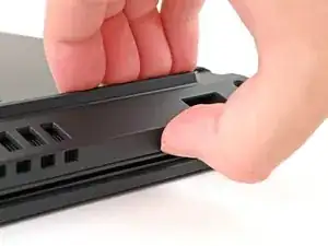
    • Insert your fingernail or an opening pick into the gap between the base cover and keyboard deck, next to one of the screen hinges.

    • Pry up the base cover until the clips unfasten.

  11. TfiDbu3MZJMfAbH5
    TfiDbu3MZJMfAbH5
    dWT63QX2xkBGKDAU
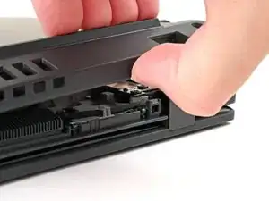
    • Grasp the base cover along the screen hinge edge and lift slowly to unfasten the remaining clips.

    • Lift and remove the base cover.

    • During reassembly, lay the base cover into the frame, inserting it into the tabs along the battery edge. Press down firmly around the perimeter to reengage all the clips.

  12. RchQcdKncTqIInbP
    RchQcdKncTqIInbP
    nsE3pK6bZYuMKZeJ
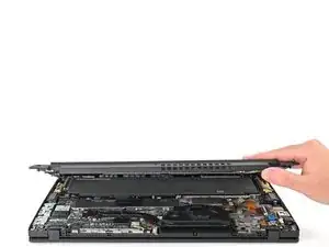
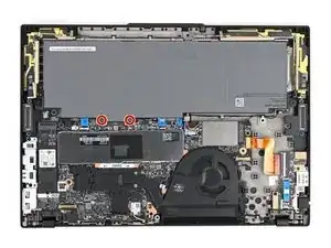
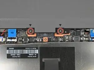
    • Because of the battery connector's design, the only way to disconnect the battery is by physically removing it.

    • Use a Phillips screwdriver to fully loosen the two captive screws securing the battery connector.

  13. A5Qc4X5veN3fKXeT
    A5Qc4X5veN3fKXeT
    mDEbvvYaOulCbZUu
    Lx4jqMVNxBI51RlL
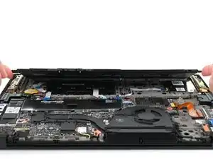
    • Lift the edge of the battery with the connector to disconnect it.

    • You may feel a little resistance from the battery connector as it disconnects—that's normal.

    • Remove the battery

    • During reassembly:

    • Slide the plastic tabs on the long edge of the battery into their recesses in the frame.

    • Lower the battery into place so the connector goes over its socket.

  14. 4KGqU4RsITHutYZP
    4KGqU4RsITHutYZP
    wTMQSWIwIZoWyn5s
    aAlSq4rsfyVVfe3m
    • Use the flat end of a spudger or clean fingernail to gently push under the metal buckle of the camera cable connector to unclip it.

  15. wwO3kyYAcKjVNciY
    wwO3kyYAcKjVNciY
    J5dx6Sgvlot2pNSC
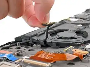
    • Grab the buckle and cable together and gently pull the connector straight out of its socket.

  16. GbBGnvkQ1EFZAfjh
    GbBGnvkQ1EFZAfjh
    OjlRCjuYhwYjfYMZ
    lVRIgkAUsPnDbUEn
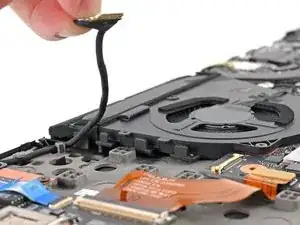
    • Hold the buckle and cable together and remove the cable from the clips holding it to the fan.

  17. LebH5kPBZIpUvGEG
    LebH5kPBZIpUvGEG
    Ykrvg5iAGqXIuR6E
    JJltm2YeSgwo1fOL
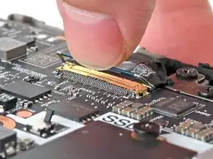
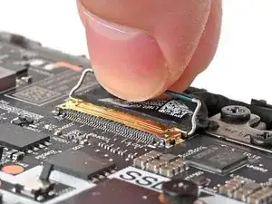
    • Use a clean fingernail or the flat end of a spudger to gently push under and lift the metal buckle of the display cable connector to unclip it.

  18. ZDitMViYlSHN23ho
    ZDitMViYlSHN23ho
    S36WC5rJxoySlmfZ
    • Use your fingers to grip the display cable buckle and gently pull the connector straight out of its socket.

  19. oEjgKkAhkQFcjVBE
    oEjgKkAhkQFcjVBE
    ljd2GPpcUMhCWOoH
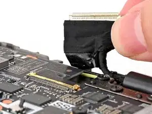
    • Hold the buckle and cable together and pull up to separate the adhesive securing the cable to the motherboard.

  20. 5X1tKHhFqC2YxQyD
    5X1tKHhFqC2YxQyD
    XWB6QCC3JPujQH26
    AJWtsAnspY1T4Qjf
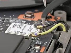
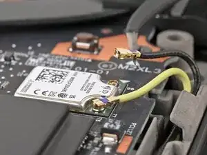
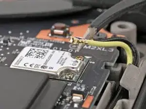
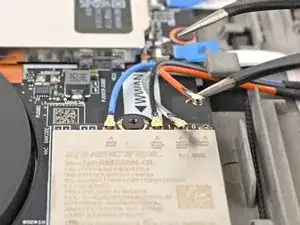
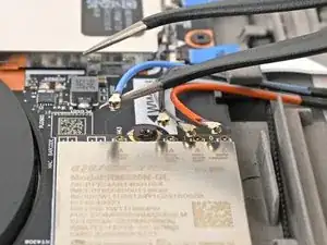
    • Insert an arm of your angled tweezers under the metal neck of one of the coaxial connectors on the Wi-Fi card and lift straight up to disconnect it.

    • Repeat for the other connector.

    • During reassembly, use tweezers to hold the connector in place over its socket and gently press down with your finger or a spudger—the connector should "snap" into place. If you're having trouble, reposition the head and try again.

  21. 5qXRyI3gfHbkJvfE
    5qXRyI3gfHbkJvfE
    bDy2BHukRfIRIEMi
    onxkQYXqZRSC2dHe
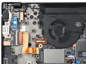
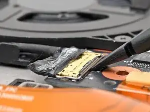
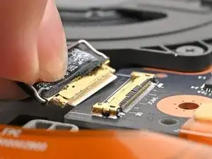
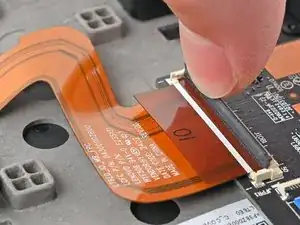
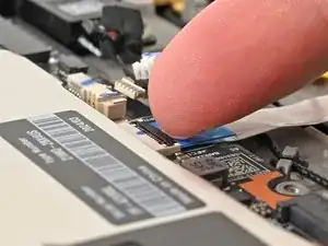
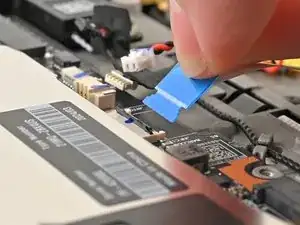
    • Use a clean fingernail or the flat end of a spudger to flip up the locking flap on the I/O board interconnect cable connector.

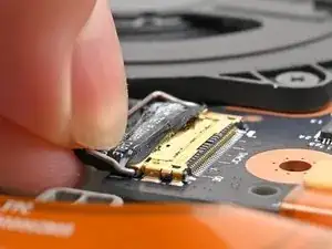
    • Use tweezers or your fingers to gently pull the cable by its pull tab out of its socket.

  22. 62G6wASNxt6sUrWM
    62G6wASNxt6sUrWM
    DUijanaumXsSjjDl
    YRSktg4jPVHFoVYB
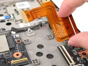
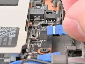
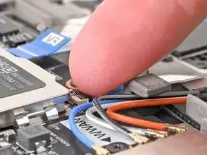
    • Insert the flat end of a spudger or a clean fingernail under a short edge of the interconnect cable press connector (located on the motherboard) and pry up to disconnect it.

    • Remove the interconnect ribbon cable from the laptop.

  23. 2huBlShST5SENE5o
    2huBlShST5SENE5o
    BHoaDVgTfsgKVLFb
    Mblun4c1WcUSKZHm
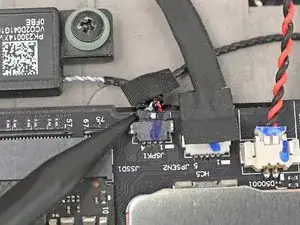
    • Use your fingernails to grip the right speaker connector by the lip near the back and gently pull the connector out of its socket (labeled"JSPK1").

    • Alternatively, you can use the point of a spudger to push on alternating sides of the connector to walk it out of the socket.

    • Unplug the connector from the motherboard.

    • Many of these connectors have a small marking that shows which side of the connector should be facing up. To reconnect, align the connector and use a spudger or clean fingernail to push it fully into the socket.

  24. Ut6NBUxoUEo2TAP1
    Ut6NBUxoUEo2TAP1
    tEPGmpYoOnysGJQm
    FHbKp3wDSvJpFqVy
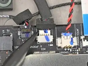
    • Use your fingernails to grab on the lip located at the back of the WWAN antenna connector labeled "JPSEN2."

    • Alternatively, you can use the point of a spudger to push on alternating sides of the connector to walk it out of the socket.

    • Unplug the connector from the motherboard.

  25. YwlEjjUZOlUtuZZe
    YwlEjjUZOlUtuZZe
    XiWkJ6vcdTdGIJtk
    SyC5SqrylDFYRURw
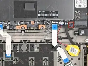
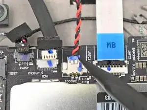
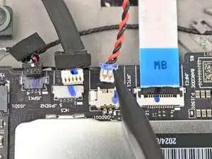
    • Use your fingernails to grab on the lip located at the back of the CMOS battery connector, labeled "JRTC1."

    • Alternatively, you can use the point of a spudger to push on alternating sides of the connector to walk it out of the socket.

    • Unplug the connector from the motherboard.

  26. TMrLpZVROMFqF4UP
    TMrLpZVROMFqF4UP
    fBLLuyrSPRigUfUR
    sJqGYNBLZrSSpucB
    • Use a clean fingernail or the flat end of a spudger to flip up the locking flap on the NFC interconnect cable ZIF connector, labeled "JNFC1."

    • Use tweezers or your fingers to grip the cable's plastic pull tab and gently pull the cable out of its socket.

  27. 6rULvXjiuFVLeEJc
    6rULvXjiuFVLeEJc
    KpgVYSUhZVemeJV5
    GqPvObQbYPUXWIOh
    • Use a clean fingernail or the flat end of a spudger to flip up the locking flap on the trackpad interconnect cable connector, labeled "JCP1."

    • Use tweezers or your fingers to grip the cable's plastic pull tab and gently pull the cable out of its socket.

  28. oQOpmPoh4wb4WFV6
    oQOpmPoh4wb4WFV6
    C4gQoxPVVI1Hqy4q
    VTgfnSx1caiCDGuL
    • Use a clean fingernail or the flat end of a spudger to flip up the locking flap on the smart card reader interconnect cable connector, labeled "JSC1."

    • Use tweezers or your fingers to grip the cable's plastic pull tab and gently pull the cable out of its socket.

  29. IdUDVBClGFPPtDPL
    IdUDVBClGFPPtDPL
    FcwA6CbEYCR2gYRP
    nhUp34QCfyNdlAJq
    • Insert one arm of your angled tweezers under the metal neck of one of the antenna coaxial connectors on the WWAN card and lift straight up to disconnect it.

  30. Mc1iCTNaPWZVqZRo
    Mc1iCTNaPWZVqZRo
    xGsXLCE5WNow1Fpa
    vilXqJT3uHspDItQ
    • Repeat the process to disconnect the remaining antenna cables from the WWAN card.

    • During reassembly, use tweezers to hold each connector in place over its socket and gently press down with your finger or a spudger—the connector should "snap" into place. If you're having trouble, reposition the head instead of using more force.

  31. U5GlbPaKhFiUxOXQ
    U5GlbPaKhFiUxOXQ
    4qTAmmRoMDXjxNsv
    rKtSWgXSEZDM54Xo
    • Hold all the antenna cables together and guide them out of their clip on the chassis.

  32. wnyleKBwNg5BmPUL
    wnyleKBwNg5BmPUL
    KW2hYnKavwvADWqq
    • Use your fingernails to grab on the lip located at the back of the WWAN antenna connector labeled "JPSEN1."

    • Alternatively, you can use the point of a spudger to push on alternating sides of the connector to walk it out of the socket.

    • Unplug the connector from the motherboard.

  33. ZBcKV2xa2WdpYHaQ
    • Use a Phillips screwdriver to remove the three 4 mm‑long screws securing the I/O bracket.

  34. LxRAG2T2pSbDVRM1
    LxRAG2T2pSbDVRM1
    cnNMa14JOXNTGF43
    • Pick up the I/O bracket and remove it from the laptop.

  35. hoERAWFO2rVVQtO1
    hoERAWFO2rVVQtO1
    JbYPhfo3TxYAEqTT
    • Use a Phillips screwdriver to remove the 4 mm‑long screw securing the SSD to the motherboard.

  36. wctpuCOduvShx6Z3
    wctpuCOduvShx6Z3
    NKajXKONhBy3mjdk
    u5uMwwcGQU3lxnx3
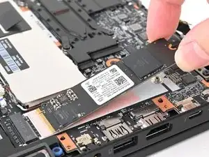
    • Use your fingernail or the flat end of a spudger to lift the edge of the SSD with a screw notch enough to grip it with your fingers.

    • Use your fingers to pull the SSD straight out of its socket and remove it.

  37. jGbDItCxBT3dAKME
    jGbDItCxBT3dAKME
    FPZ1BUDqUEY6Z6Le
    • Use a Phillips screwdriver to remove the 4 mm‑long screw securing the WWAN card to the motherboard.

  38. HLIk5atktS6hJI4U
    HLIk5atktS6hJI4U
    B5bgO2PmsrvyNFQB
    imyDXQrHg6Fwfdfm
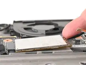
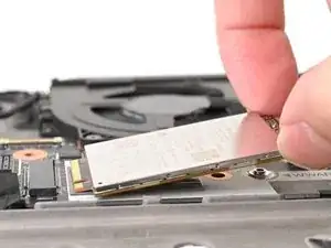
    • Use your fingernail to lift up the WWAN card enough to grasp it with your fingers.

    • Pull the WWAN card straight out of its socket and remove it from the laptop.

  39. JMNBWJEBfHHrfLCb
    JMNBWJEBfHHrfLCb
    2JwLMm4fpe1gWoxY
    • Grab the pull tab in the middle of the RAM shield and pull straight up to remove it from its clips.

    • Since the RAM shield is thin, it may bend slightly during removal. During reassembly, lay the shield into place and press down firmly around the perimeter to engage all the clips.

  40. tLP3H12UiCrSYLcm
    tLP3H12UiCrSYLcm
    RpkKsGshhYOOaXG3
    auaCxKpVeEqPGhHr
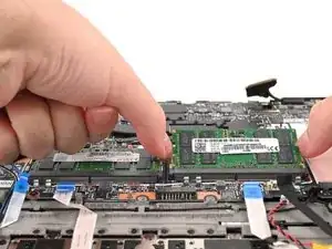
    • Use your fingers to simultaneously push the two metal tabs on the edges of the RAM module down and outwards to unlatch them—the RAM should pop up at a slight angle.

    • Remove the RAM stick.

    • Repeat the above process for the other stick of RAM.

    • During reassembly, fully insert the RAM at the angle it popped up at, then press down to engage the metal arms.

  41. MGIkJteCIEHWLFDR
    MGIkJteCIEHWLFDR
    hBeYnnGxsq6AcoTk
    • Use a Phillips screwdriver to fully loosen the five captive screws securing the fan and heatsink.

    • During reassembly, tighten the screws in an "X" pattern in the order labeled: bottom left, top right, bottom right, top left.

  42. 66M3hRAxx66gayIE
    66M3hRAxx66gayIE
    bU6yQkbymKOCYJLn
    4OLHXIkGc2pihiuF
    • Grasp the fan and heatsink assembly by its edges and remove it from the laptop.

    • You may feel a little resistance from the thermal paste and pads between the heatsink and the components on the motherboard — this is normal.

  43. cZndQCGS1NgK4tcq
    cZndQCGS1NgK4tcq
    JbUOjjrF1nASV2yU
    • Use a Phillips screwdriver to remove the three 4 mm‑long screws securing the motherboard.

  44. GoGQnDHgL6GxucvR
    GoGQnDHgL6GxucvR
    DiUab6OXoODvTgVA
    U2ZXK6tkvBw1tPDj
    • Use your finger to lift the motherboard by the edge closest to the fan.

    • Raise the motherboard to a 45‑degree angle to free the ports from their cutouts.

    • Grip the edges of the motherboard and remove it.

    • During reassembly, insert the motherboard downward at a 45‑degree angle so the ports go into their cutouts, then lower the board into place. Make sure no cables get trapped underneath the board and that the board is aligned with its screw holes.

Conclusion

Compare your new replacement part to the original part—you may need to transfer remaining components or remove adhesive and thermal backings from the new part before you install it.

To reassemble your device, follow these instructions in reverse order.

Take your e-waste to an R2 or e-Stewards certified recycler.

Repair didn’t go as planned? Try some basic troubleshooting, or ask our Answers community for help.

Nick Schultz

Member since: 24/03/24

13497 Reputation

0 comments