Introduction

Use this guide to replace or upgrade the RAM in your HP Pavilion 15 Laptop PC.

Note: This procedure was written using a model 15-eg2015od HP 15 Pavilion Laptop PC, but is fully compatible with any HP 15 Pavilion Laptop PC whose model number starts with 15-eg or 15-eh.

This laptop has two RAM slots that support DDR4 SO-DIMM memory modules.

  1. qKyNdFiAkXWsYRtH
    • Fully shut down your laptop and unplug all cables.

  2. TLPEQvvXeS53Llst
    • Flip your laptop over so the rubber feet are facing up.

  3. 6HHMPIRpK2KYmoUn
    6HHMPIRpK2KYmoUn
    kS2TRleB3syfJRrb
    WfWl3lZLP3aEarxx
    • The ends of the rubber feet cover four back cover screws.

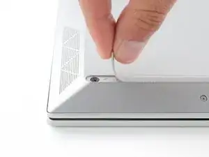
    • Use an opening pick to peel up an end of the front rubber foot until you can grip it with your fingers.

    • Make sure both the foot and its adhesive peel up together, as they need to be lifted up as one piece.

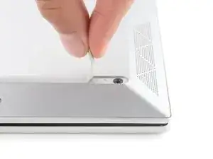
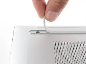
    • Peel up the end of the foot with your fingers just until the hidden screw underneath is exposed—you don't need to fully remove the foot.

  4. NeVbjR6kMExwQUaP
    NeVbjR6kMExwQUaP
    kWsuTHywX2waR1CY
    4XEnIFntjGwPR43R
    • Peel up the other ends of the feet to expose the three remaining screws.

    • During reassembly:

    • Press down firmly on the ends of the feet to secure them into their recesses.

    • If the foot adhesive doesn't remain tacky enough to readhere, you can use double-sided tape such as Tesa Tape.

  5. iWpXE2fUA1CrW2oW
    iWpXE2fUA1CrW2oW
    kwhTlPnW1eMnBWBg
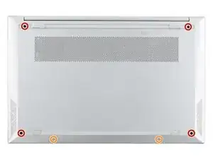
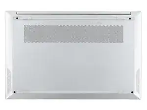
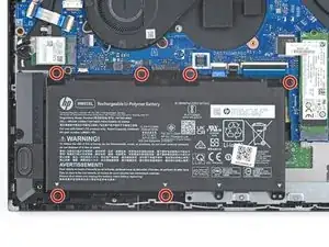
    • Use a Phillips screwdriver to remove the six screws securing the back cover:

    • Four larger 6.6 mm-long black screws

    • Two smaller 4.8 mm-long silver screws

    • Despite the standards, Phillips screwdrivers can vary in size and shape—two drivers labeled as the same size may fit differently in the same screw. Use the size that fits the most snug into the screw head to avoid stripping it.

  6. TcUv1hpK2sRKsOx5
    TcUv1hpK2sRKsOx5
    hsNx46wTmTJEXUG6
    • Tight plastic clips secure the back cover to the frame. You'll hear and feel the clips release as you work.

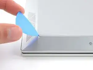
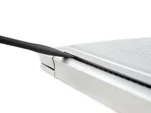
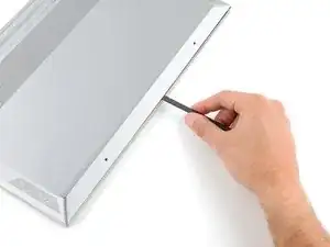
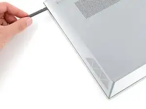
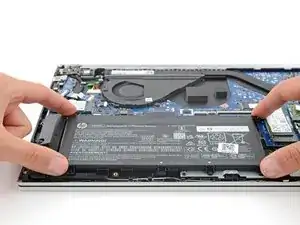
    • Insert the flat end of a spudger between the top edge of the back cover and frame, just to the left of the right hinge.

    • Pry up with the spudger to release the clips securing the top right corner of the back cover.

  7. 3tGGb6QKbZLQKog4
    3tGGb6QKbZLQKog4
    MOujvuRE5YvBpWxg
    vWHYvRW3SiG5ZP5E
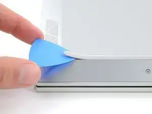
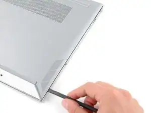
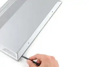
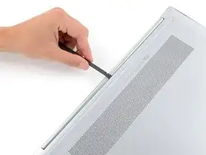
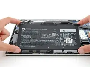
    • Insert the flat end of a spudger between the top right corner of the back cover and frame.

    • Slide the spudger down to the bottom right corner to release the clips on the right edge.

  8. AJV6vbhBJXPWIiKX
    AJV6vbhBJXPWIiKX
    BvnObI2thitLViyk
    vtBLrJOU1lqaipbZ
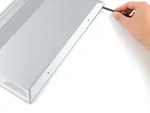
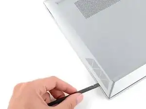
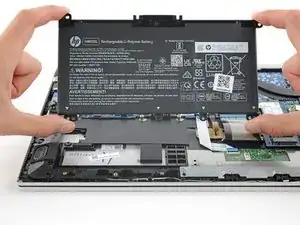
    • Insert the flat end of a spudger between the bottom right corner of the back cover and frame.

    • Slide the spudger to the bottom left corner to release the clips.

  9. KVmgjswfhBMnOlBF
    KVmgjswfhBMnOlBF
    mY1C4ARXBvwGZJOo
    CYLUFKmZMPKW3jIK
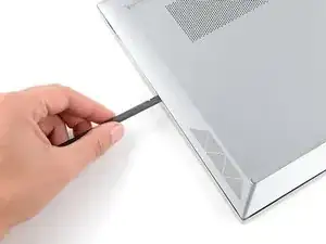
    • Insert the flat end of a spudger between the bottom left corner of the back cover and frame.

    • Slide the spudger up to the top left corner to release the clips on the left edge.

  10. BTUVN2Cj2QW4BIOp
    BTUVN2Cj2QW4BIOp
    2l4auZLCEPT1v2wT
    KYyr2MQQ1sAOPTt4
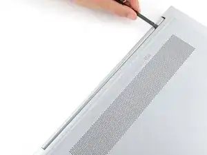
    • Insert the flat end of a spudger between the top edge of the back cover and frame, just to the right of the left hinge.

    • Slide the spudger towards the right hinge to release the remaining clips.

  11. xjAZfJ5UgQIFJMU4
    xjAZfJ5UgQIFJMU4
    oaMeuHIJpw4PEZHa
    w6P12TYsWvyDbTIP
    • Remove the back cover.

    • To reinstall the back cover, lay it on the frame and firmly press down around the perimeter to engage all the clips.

  12. epTThRQTlvTFYtaI
    epTThRQTlvTFYtaI
    nFN3TIX2jkd4TTvS
    • Given the design of the battery connector, the only way to disconnect the battery is to physically remove it.

    • Try not to bend, crease, deform, poke, or puncture the battery with your tool—a damaged battery is a potential fire hazard.

    • Use a Phillips screwdriver to remove the six 3.9 mm-long screws securing the battery.

  13. mtkHjWhkEd5KPQNK
    mtkHjWhkEd5KPQNK
    MooRDWNOBQlygeui
    ANR1Cu5pCd56E3J2
    • Gently lift the upper edge of the battery to disconnect its socket from the motherboard.

    • Remove the battery.

    • During reassembly, use the alignment posts to position the battery and press down on the socket to secure it.

    • Never reuse a deformed or damaged battery—it's a fire hazard. Replace it with a new battery.

  14. KDFgEsKrUo3fJZBQ
    KDFgEsKrUo3fJZBQ
    Vv1IBoLGJZXfZOsp
    aBKfQhGoBkUWKArr
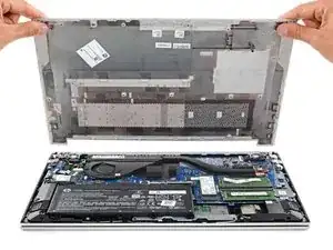
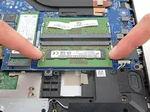
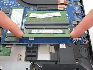
    • Your laptop has two memory slots, each with a pair of metal arms that secure a stick of RAM.

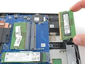
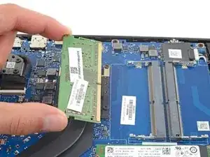
    • Simultaneously push out the metal arms on each side of a stick of RAM until they disengage and the stick pops up at a slight angle.

  15. 6sVpIJGbNIOVHJaX
    6sVpIJGbNIOVHJaX
    D45jiemA4wAYebj6
    smAKJVJrkvTWOYPV
    • Pull the stick of RAM out of its socket to remove it.

    • Repeat for a second stick of RAM.

    • To install a memory module, insert it into its socket at a slight downward angle, then push down firmly until both metal arms lock the RAM in place.

Conclusion

To reassemble your device, follow these instructions in reverse order.

Take your e-waste to an R2 or e-Stewards certified recycler.

Repair didn’t go as planned? Try some basic troubleshooting, or ask our Answers community for help.

Spencer Day

Member since: 14/09/22

88286 Reputation

3 comments

hello,

This is a very useful document with great pics & steps to follow for customers who are looking to upgrade their RAM. Thank you for creating this document. I would like to know if this content is available in English only?

And, if its available in other languages, can you please let me know what languages are offered?

Thanks & Regards,

Vasundhara

Vasundhara -

Very clear and easy to follow :)

Tom Chapman -

Solid guide, cheers. All outer case screws use PH00 screws, I used PH1 for the fans.

FarmYard Gaming -