Introduction

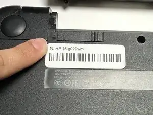
This is a guide on how to replace the RAM on your HP 15-g029wm. This guide may be needed if you're encountering problems with your HP 15-g029wm's screen freezing. There is only one step in this guide that describes how to remove the RAM from your motherboard to replace it.

  1. L1mvMIFD6dnsx3wE
    • Unplug any charging cord or accessories connected to the device before beginning.

  2. HYZNZDhWbgAZ1XIu
    • Place the laptop bottom-side up on a secure, flat surface.

  3. rfcESNBDQb4GSsBF
    rfcESNBDQb4GSsBF
    cRy6FhROsYRmCcUD
    FWCI6xnnLvyrHceD
    • Slide each of the two switches that secure the battery to the left.

    • This will reveal an image of an unlocked lock.

  4. KOCkBxLGybMC4nE3
    KOCkBxLGybMC4nE3
    URF1YoapUg1W1jPL
    QmfALseeldUZxHAg
    • Use your hands to gently pull the disconnected battery out of the device.

    • When inserting the new battery, pay special attention to align the battery connections correctly.

  5. fxrPI2lK1sHoUnD6
    fxrPI2lK1sHoUnD6
    V6DJI1mqtVwRBfyJ
    • Remove the following Phillips screws on the lower case:

    • Nine 5 mm

    • One 6 mm

    • This will allow the optical drive to separate from the chassis.

  6. hmLh6OVxAUViBe1N
    • Slide the optical drive directly out of its slot.

  7. OctAX5ORKpnZQXuX
    • Remove the two 2 mm Phillips screws on the lip of the optical drive slot.

  8. EPLBcSQHGXbfEb5P
    EPLBcSQHGXbfEb5P
    mloYwQqEXRMEbXSI
    5KRylwOEaB41QsEM
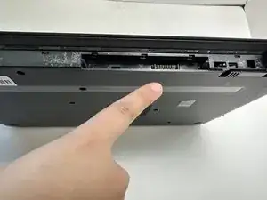
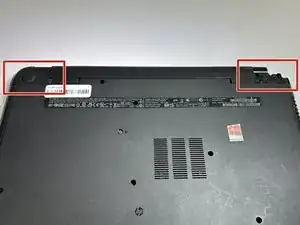
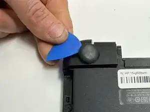
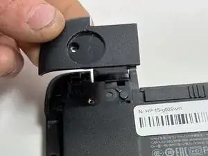
    • Use an opening pick to remove the two circular rubber feet near the laptop hinges.

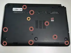
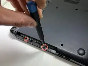
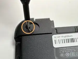
    • Remove both of the 8 mm Phillips screws.

    • The screws were hidden by the rubber feet.

  9. xuGcKWLIa4wSDmvm
    xuGcKWLIa4wSDmvm
    coVNRRDorK2A2KqV
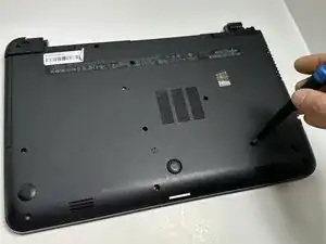
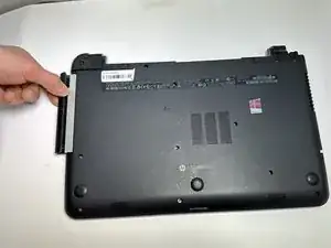
    • Use an opening pick to pry up and remove the left hinge cover.

    • Use an opening pick to pry up and remove the right hinge cover.

  10. NKKDHWni124Q2FqM
    NKKDHWni124Q2FqM
    UaaL2XDevmsEV2FM
    YJgLJ6NZoGaadNfJ
    • Flip the device face up and open the lid.

    • Insert an opening pick under the keyboard and pry around the perimeter of the keyboard until it fully releases.

    • Lift the keyboard slightly.

    • There is a ribbon cable connecting the keyboard to the device on the underside. Do NOT pull it away or you risk ripping the ribbon cable and causing damage.

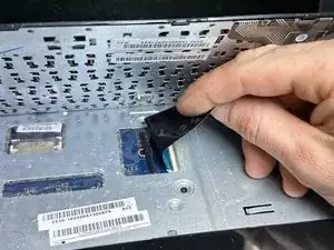
    • Use your fingers or an opening pick to unlock the ZIF locking flap that secures the keyboard ribbon cable.

    • Disconnect the keyboard ribbon cable.

    • Lift the keyboard off.

  11. JccwEOU4ykyRDHFS
    JccwEOU4ykyRDHFS
    bFXCW5oAIEv1epbQ
    TVLDtmDJEAqKPbch
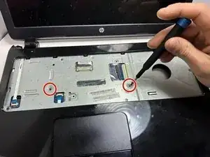
    • Remove two 5 mm screws using a Phillips screwdriver.

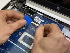
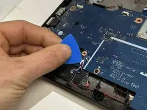
    • Insert an opening pick in the seam between the top case and chassis.

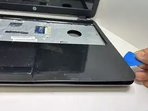
    • Slide the opening pick around the edge of the device to separate the top case from the chassis.

    • Slightly lift the top case up and away from the chassis.

    • There is a ribbon cable connecting the top plate to the device. Handle with care, and do NOT yank on the ribbon cable to prevent damage.

  12. CofZwsRSxUeNMDPe
    CofZwsRSxUeNMDPe
    jSZWpDfjCQ1qxxPI
    WTZUCJ1gUMFIcSHO
    • Use your fingers or an opening pick to flip up the black ZIF locking flap.

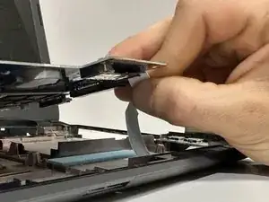
    • Disconnect the ribbon cable.

    • Lift off the top case.

  13. ewNDkkRaJ5evJHvY
    ewNDkkRaJ5evJHvY
    NUvP5JKHEPYQVpUD
    • Use a Phillips screwdriver to remove the three 5 mm screws that secure the fan.

  14. ZilA4CrpMslaSfsW
    ZilA4CrpMslaSfsW
    f3SJmb5E3pbRTgDL
    • Gently "walk" the fan connector directly out of its motherboard socket.

    • Do not pull on the wires.

  15. 4hAKPaqVYsorSHMK
    • Lift the fan up and out of the chassis.

  16. ELeDCALAuRJvnIwH
    ELeDCALAuRJvnIwH
    NWOekDmWfgrFD6SK
    MeUbvTSgkvC1kaHE
    • Use two opening picks to disconnect the display cable.

  17. JLAdSQycu3FJC41B
    • Use an opening pick to gently "walk" the white speaker connector directly out of its port.

  18. bXdODJw1fwPVnGKu
    bXdODJw1fwPVnGKu
    tfDssZVVpNcZetLg
    1GJM6C2DWaJgL3IX
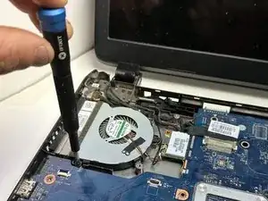
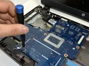
    • Remove the four 3 mm screws that secure the motherboard.

    • Lift the front edge of the motherboard slightly.

    • There is a ribbon cable connecting the motherboard to the device chassis. Do not yank it away.

  19. vQB4EWP2tgLAK2X4
    vQB4EWP2tgLAK2X4
    5aVEcItZyAeZkn3m
    aEI3AnsZMkSogOtH
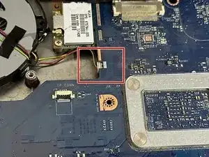
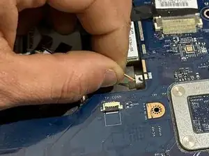
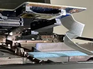
    • Use an opening pick or your fingers to release the ZIF locking flap.

    • Pull the ribbon cable out of its port.

  20. 16OEw1AlNc2TQMRI
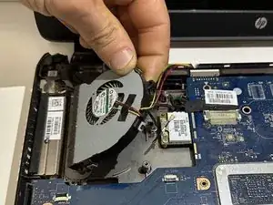
    • The motherboard is now fully disconnected and able to be removed from the chassis by lifting it out with your hands.

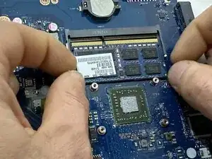
    • Remove the following components for your new motherboard: Heatsink, RAM, CMOS battery.

  21. LuxImYSCDy5rPWVA
    • Two clips secure the RAM module in place, one on each side. Using your fingers, spread the clips away from the RAM module

    • When released, the RAM modules will pop up at a slight angle.

    • Slide the RAM module straight out of its socket.

Conclusion

To reassemble your device, follow these instructions in reverse order.

Lawrence Bailey

Member since: 29/01/24

208 Reputation

0 comments