Introduction
This is a step-by-step guide to replace the screen of your Abask J05 dashcam.
The screen is a 1.5” thick, double-layered pane of glass with a thin liquid crystal layer in-between. Its function is to display information. A broken or faulty screen could prevent information from being displayed properly. If your screen flickers uncontrollably, freezes repeatedly, and/or turns black/white, it might be in need of replacement. Before replacing the screen, be sure to review the troubleshooting guide as there might be other reasons your screen is malfunctioning that don’t require replacement.
-
-
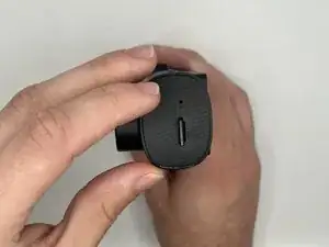
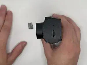
Gently press on the SD card with a fingernail until it clicks.
-
Release, then remove the card.
-
-
-
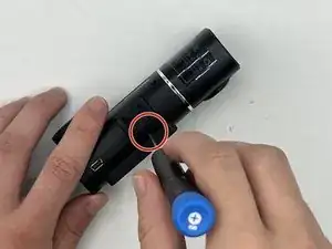
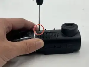
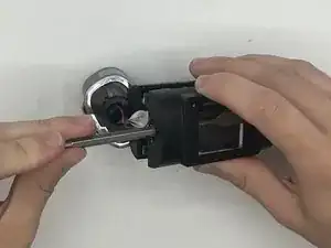
Remove the 5 mm screw from the side of the device next to the suction cup dock with a Phillips #00 screwdriver.
-
-
-
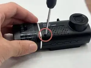
Remove the two 8 mm screws from opposite sides of the screen with a Phillips #00 precision screwdriver.
-
-
-
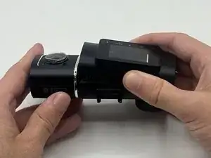
Gently lift the screen.
-
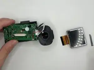
Push up on the interior camera portion of the device. It should pop out of the socket. Being careful to keep the wires attached, set it to the side.
-
-
-
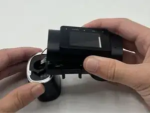
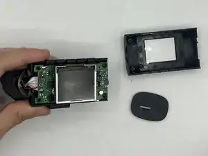
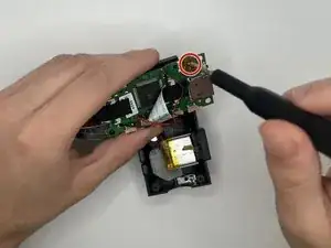
Reach into the device with a spudger to release the top two snap joints keeping the end cap attached one at a time until the front face lifts off.
-
Repeat the process with the two remaining snap joints.
-
-
-
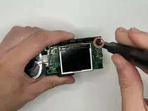
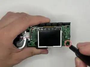
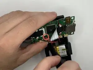
Remove the two 7 mm screws on the side of the motherboard with a Phillips #00 screwdriver.
-
Slowly pull up on each corner of the motherboard, stopping when the corner pops loose of the anchor.
-
Repeat the process with each corner before slowly pulling up on the board to detach the glue on the underside.
-
-
-
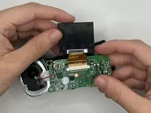
Carefully flip over the motherboard, being mindful of the wires.
-
Remove the two 5mm screws on the underside of the motherboard with a Phillips #000 screwdriver.
-
-
-
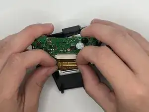
Follow the golden ribbon from the screen to the screen dock. Push the two small black stubs on either side of the dock away from the dock until it pops loose.
-
Remove the ribbon and the small plastic piece from the dock.
-
-
-
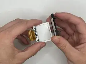
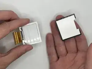
Gently pull up on each corner of the white screen piece until the adhesive comes loose.
-
Remove the screen fully from its holder.
-

To reassemble your device, follow these instructions in reverse order. (Note: When doing the steps in reverse order, do not do Step 5. Instead, place the front face of the device back on the main body before lining up the endcap, ensuring proper orientation with the SD card slot, and push in until you hear all four snap joints snap into place.)