Introduction

This is a teardown of a Samsung WB690 bought second-hand. It contains large capacitors for the camera flash, which can shock you if you're not careful. If you follow these steps yourself, proceed with caution and make sure you know what you're doing. If you decide to disassemble a working lens, or partially working lens, be prepared for high chance it won't work at all afterwards.

  1. P4cFAhNU2nITrkOa
    P4cFAhNU2nITrkOa
    IjpUNwVLCPMjHbQV
    dEamGCTIhmHRujwe
    • Remove the battery by pressing in the blue tab.

  2. Sw4GGFd2TTiDRCAl
    Sw4GGFd2TTiDRCAl
    dB1wHWYNuLNQxfuN
    Uj4P4JwCFrwrNugj
    • There are 5 Philips #0 screws in total.

  3. fSACawvuVNXUf3ty
    fSACawvuVNXUf3ty
    CIWa1vqCJeyUCOha
    XCsDkusqSxKuUC2Q
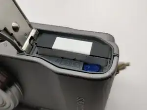
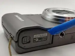
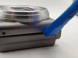
    • First, ensure the cover is at least mostly unclipped on all sides.

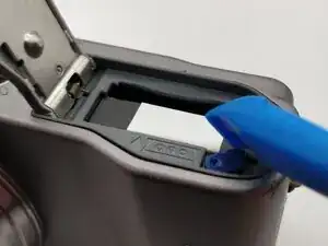
    • Then, focus on fully popping off the front cover. Prying in the position shown above the battery cover is the most consistently effective. You may need to use a bit more force for this step.

  4. LveqC4ytlv5EdHnf
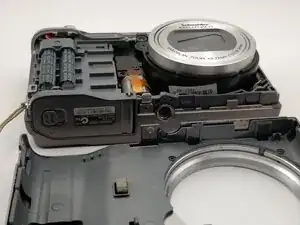
    • Be careful not to touch the capacitors or the internals of the camera.

    • Even if the battery has been removed, the capacitors likely still hold a charge, enough to give you a nasty shock.

  5. EQQJrH3QFekEQ4Hd
    EQQJrH3QFekEQ4Hd
    r5dCoRXuafj6xyJh
    GV3R1spgj2NGRYmr
    • Showing how the clips line up

  6. HVrD6Bs1BfVeQAqw
    HVrD6Bs1BfVeQAqw
    omwI5NBICkFBaIZg
    Pba5Te3sCgOeLxPY
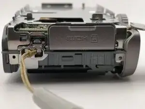
    • Set your multimeter to the highest voltmeter setting (e.g. 600V on the one shown) and ensure the probes are connected to the correct terminals.

    • Connect the red probe to the solder on the red wire and the black probe to the solder on the black wire.

    • WARNING: Be careful not to touch the two probes together while doing this. It would short-circuit the capacitor and dump a large amount of charge very quickly. Also be careful not to touch the metal on the probes.

    • Look at the meter reading. It could start in the >300V range. If you don't see a reading, make sure the probes are making a good connection. If they are, and you still don't see a reading, drop the voltmeter setting a couple of notches (e.g. to 20V) and try again. The capacitors may already be (mostly) discharged.

    • You should see the voltage dropping as the capacitor discharges through the multimeter.

    • Continue to discharge until the voltage reduces to a significantly lower level (e.g. <20V), then switch to a more sensitive voltmeter setting (e.g. 20V) to maintain accuracy and continue discharging.

    • Discharge speed will slow down the lower the voltage gets. Once it slows to a crawl at a low voltage (<10V), you can intentionally short-circuit the capacitor with the probes to quickly discharge the remaining charge.

    • Verify the capacitors are fully discharged using the multimeter at a more sensitive setting (e.g. 2V). The reading should be at or close to 0V. Note: If the reading starts increasing it's because the multimeter is starting to charge the capacitors. Short-circuit them one last time and turn off the multimeter.

  7. 2XnnYZJYx5hLvVwk
    2XnnYZJYx5hLvVwk
    LXtHDXgJFRPExMUp
    psB5FRZfMdfZ5ETe
    • As with the front cover, start prying off the back cover on all sides except the top

  8. 63Uc5JxmXDWeTWxW
    63Uc5JxmXDWeTWxW
    awGs3Jt6NGAAOhDk
    AlrO21EeaMAXHxOw
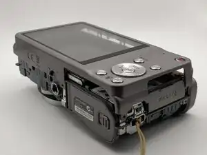
    • The trickiest part is corner by the HDMI cover. The arrow in the second image points to where the plastic cover is sandwiched between two other pieces. Don't apply extra force to the back cover until this clip is popped out.

  9. BtyAUDYfhILRiaHm
    BtyAUDYfhILRiaHm
    eKItcJMAvLBAovdK
    • Popped back cover

  10. VXQgxxewYJL6TFlN
    VXQgxxewYJL6TFlN
    BhtXAyJOWBuJOxCS
    ZcPmdyydApYOq3MZ
    • Lining up cover.

  11. JAcMrMOXRqMUh3bg
    JAcMrMOXRqMUh3bg
    iAHPLiE3iMNVXAOQ
    • Unscrew the board.

    • Flip it out of the way.

  12. NywnsWrXjCR4XVwT
    NywnsWrXjCR4XVwT
    d1SwFfZ6xmNhIIGO
    GFxDXnCtJAY4sJcr
    • Unclip the ribbon cable with a pry bar.

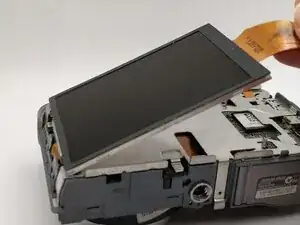
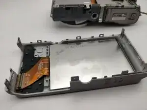
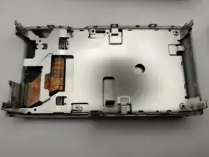
    • Remove the screen. It might be slightly stuck on one side with glue, but it should come off without much effort.

    • Place it face down in the back case to protect the screen.

  13. qhQLTXp6TYYn2AIn
    qhQLTXp6TYYn2AIn
    1wjFkelu4spP4QE4
    YMEtk5wHXFFFDWhK
    • Remove the screw holding on the backplate.

  14. 6aBKVnTeOCCXFsxo
    6aBKVnTeOCCXFsxo
    KQob4CUSgWRVLMjt
    Se3YmGRfN1Fj6I42
    • Pop off the backplate.

  15. IKESPkwp1QygoMZs
    IKESPkwp1QygoMZs
    D61AJTScWdBeecao
    • Put the backplate with the back cover to the side.

  16. 2Tk2XVMJhibxPQKZ
    • The main board.

  17. ADLkqorX55ptXTPU
    ADLkqorX55ptXTPU
    4NbTnhHxS3t3etk4
    LD2K3hhcFx1UJN2a
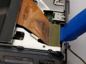
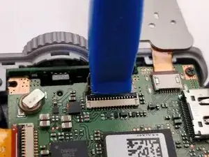
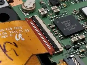
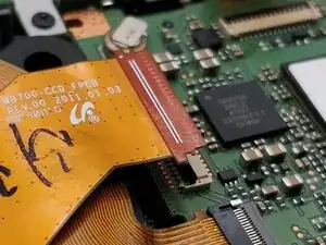
    • Unclip the main board ribbon cable with a pry bar by pulling the black tab up and away from the cable.

    • Remove the ribbon cable from the slot.

  18. CpnWR6KkDvtRSrxF
    CpnWR6KkDvtRSrxF
    L4vNUueBCTF5BUUD
    nHM1nFkgpuOXrphW
    • Unclip the CCD ribbon cable with the same method as the main board cable.

  19. 5W1ytdwY2dVX4sZp
    5W1ytdwY2dVX4sZp
    bYRf6hSnKGJacrjm
    QW4P4ZpWChRHOS4Q
    • Unclip the lens ribbon cable. Unlike the previous two, pull up and towards the cable.

  20. TugOBYXdMS2CVKTD
    TugOBYXdMS2CVKTD
    AsUBNDsuZUNcIldB
    oPeWtmapZYrRCRvA
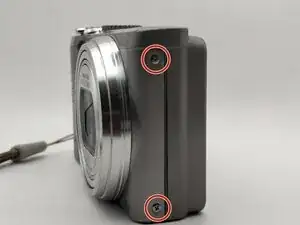
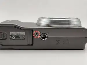
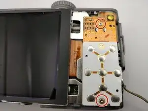
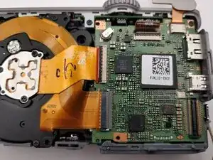
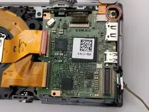
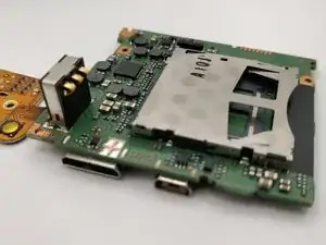
    • Remove the screw holding in the main board.

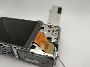
    • Remove the main board, pulling up and away from where the ports are poking through. You may want to help unstick the ports by pushing on them from the outside at the same time.

  21. cUQbOuSSnpuKHZhq
    cUQbOuSSnpuKHZhq
    Lv2hSUOID5GkaNnP
    • Flipping over the main board.

  22. MAcpkGhPpYej5Hqi
    MAcpkGhPpYej5Hqi
    OIFmRJZXoxCPCAI3
    • The lens is now free from the case.

  23. MWbmdQDX3cGN6IeV
    MWbmdQDX3cGN6IeV
    hOpI1SEnfuWn2QSl
    aLcMXkKo5TvlgY2a
    • The lens module.

  24. Te4Wx6BefBPU46CB
    Te4Wx6BefBPU46CB
    JX6uqtJmvRTbaOOe
    ISCxjDh3qgUO5slq
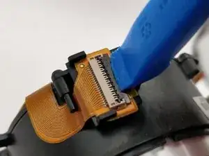
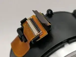
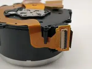
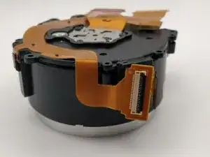
    • Unclip the side ribbon cable.

    • WARNING: If your lens is currently working, there's a high chance the following steps will break it. There are a lot of moving parts and correct reassembly is tricky. Even if you do reassemble it correctly, you might introduce extra friction which will cause the lens to jam.

  25. 6nwOWiHIOAONWjPr
    6nwOWiHIOAONWjPr
    KgA2qpOll4ZPhMK2
    aSBqZomFnYN4Usbn
    • Remove the board from the plastic restraints. You will have to pull on the cable a bit.

  26. huD1pJ1QHdySxFAg
    huD1pJ1QHdySxFAg
    POpJce2AAU5Gk3sU
    HFvkL2UKcHFjd2PU
    • The back of the lens is now free.

  27. yZhDWuJgSxEYdZ4F
    yZhDWuJgSxEYdZ4F
    4GgdhkaaVUERYARV
    • The focusing mechanism.

  28. UddUyKhxmNuqS5Zo
    • The lens with optical image stabilisation (?)

  29. sAotURXvYBOWfMZv
    sAotURXvYBOWfMZv
    gJUt4PSZK6Te3FKV
    5EboZymDPF2IZ6WS
    • This gear connects the motor to the zoom mechanism.

  30. Tvs5WZViSXtrWBGG
    Tvs5WZViSXtrWBGG
    mD2xbEMnkpPPnirI
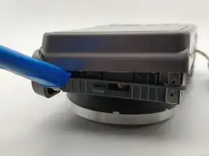
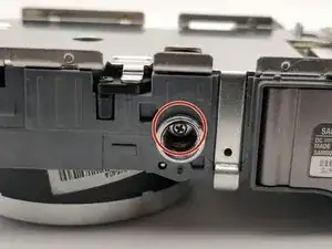
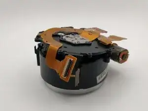
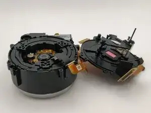
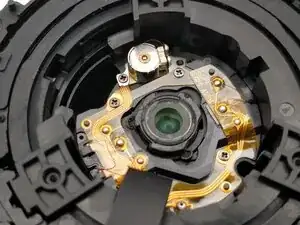
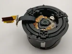
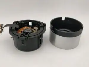
    • Push down on the lens to remove it from the outside housing.

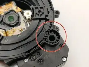
    • Note the alignment highlighted by the red boxes.

  31. t1McpGCKFTMuloSt
    t1McpGCKFTMuloSt
    iq2bdJ4vtGXQRPvS
    qOvVcfZLXDRu3W1w
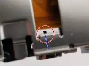
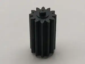
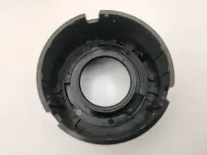
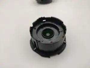
    • The circled nubs follow the tracks on the inside of the housing, translating rotation into linear motion extending the lens outwards.
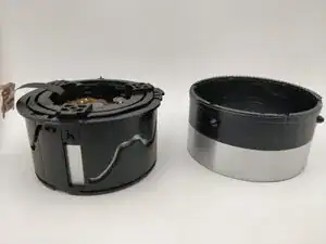
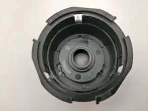
  32. YMP1Hx1cDXyCKqZJ
    YMP1Hx1cDXyCKqZJ
    LNaXfvQ3ERpgDGSS
    • Remove the next layer.

  33. klplL4HOmd4IWFib
    klplL4HOmd4IWFib
    rE6Dwtr4y1OlMVdr
    • Track and follower alignment.

  34. UxETNORbivHoOcAF
    UxETNORbivHoOcAF
    nFWUP4wmEIUHLEyx
    BNtGohWXTWnI3JEd
    • Remove the next layer.

  35. 1OFha11xeITENXmW
    1OFha11xeITENXmW
    3sxYWmjk5NGEgxPQ
    • Track and follower alignment.

  36. sWtCqLrEbkAJuS1u
    • Remove the next layer.

  37. K5iDQu2BDpJOQEW2
    K5iDQu2BDpJOQEW2
    ROk3KkV1aALVG4hh
    • Track and follower alignment.

  38. ZFUDIiVWrUPoKJX6
    ZFUDIiVWrUPoKJX6
    Fqi5UwWDi2TkExPD
    hIlm3SnRm3XLBcv1
    • Remove the next layer.

  39. jETE4OEZNSne2rTI
    jETE4OEZNSne2rTI
    vwlWj4S5HffOJ5PS
    MQg4qVRkhXGDnSJs
    • Layer alignment.

    • Most layers have a rotational symmetry of order 3 (i.e. they're identical after rotating them 120 degrees), but these layers have one correct orientation.

    • The circled parts of the two layers must align. Pushing the aligned layers together closes the outer lens cover.

  40. nVlD51TKtMMXadso
    nVlD51TKtMMXadso
    seAQ6KEGbo52buEL
    aY5aPvFnXLEt1ZOX
    • Remove the next layer.

  41. M3Jx5gyjCEVUGE3P
    M3Jx5gyjCEVUGE3P
    sLPCRBkCVhL6kKtF
    • The last piece.

Jess

Member since: 11/03/25

553 Reputation

0 comments