Introduction
If the control sticks on your Xbox Duke Controller aren't registering input or are registering input when you aren't touching them, use this guide to replace them.
Before using this guide, check to see if there is any dirt or debris clogging the space between the controller and the control stick. Spraying a small amount of contact cleaner into that space and rolling the control stick around can potentially fix the issue. Otherwise, the problem may lie with the potentiometer inside the controller.
A small amount of contact cleaner directly in the potentiometer may work, otherwise they will need to be replaced. Follow this guide up to Step 2 to open up the Duke controller and separate the two halves.
-
-
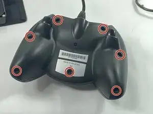
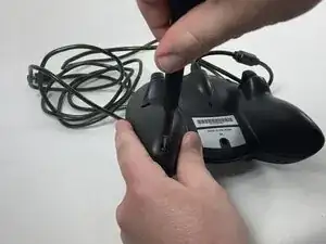
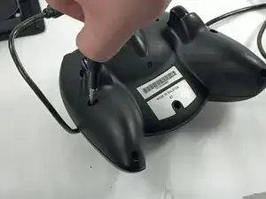
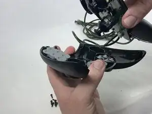
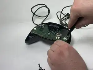
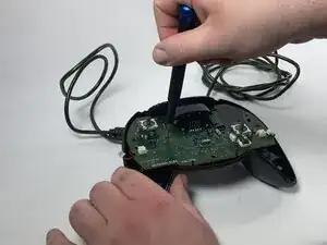
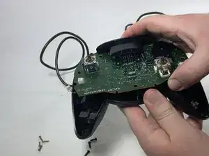
Remove the seven black 8 mm screws holding the two halves of the Duke together using a Phillips #1 screwdriver.
-
-
-
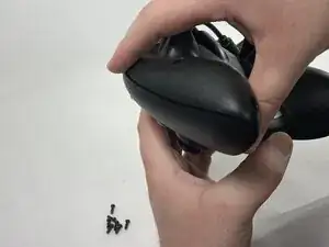
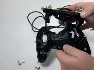
Remove the two halves of the Duke, placing the top plate face-down so the buttons don't fall out.
-
-
-
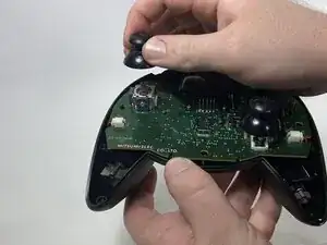
Disconnect the connectors attaching the rumble motors to the motherboard using a pair of tweezers.
-
-
-
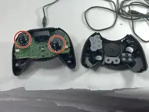
Using a Phillips #1 screwdriver, remove the four yellow 8 mm screws holding the motherboard to the bottom half of the controller.
-
-
-
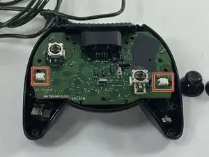
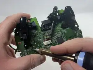
Desolder the connector pins holding the left trigger assembly in place.
-
Remove the trigger assembly by pushing on the black connectors that hold them to the motherboard.
-
-
-
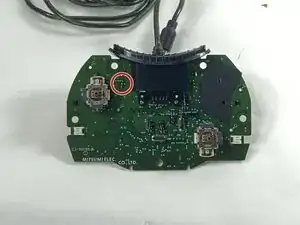
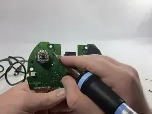
Desolder all of the connector pins holding the potentiometer in place.
-
Pull out the potentiometers and solder the new ones into place.
-


To reassemble your device, follow these instructions in reverse order.