Introduction

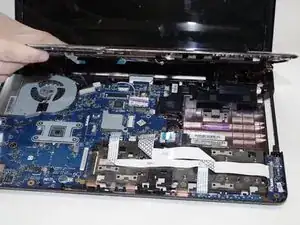
Replacing a motherboard is a crucial step when upgrading or repairing a computer because it serves as the central backbone of the entire system. All critical components—such as the CPU, RAM, GPU, and storage devices—connect through the motherboard, making it essential for system performance, compatibility, and functionality. Over time, older motherboards may become outdated or fail due to wear, preventing users from running modern software or hardware. By replacing the motherboard, users can extend the life of their computer, improve performance, and take advantage of the latest technological advancements. In this guide you will learn how to replace the motherboard on a Toshiba Qosmio X775-3DV80.

  1. fNAMohyBN5k6K1ZQ
    fNAMohyBN5k6K1ZQ
    oAjryetdMBAxH3Ze
    • Turn your laptop over so the underside is facing up.

  2. iJwPuVJCNVpdTXHF
    iJwPuVJCNVpdTXHF
    OOqjEdPSJblAiZDC
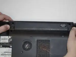
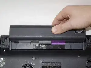
    • Identify the two sliding locks on either side of the battery.

    • Simultaneously slide both locks outward to release the battery.

  3. WhOuj4gNYbKH3XSR
    • Pull the battery straight out of its slot to remove it.

  4. diWufTZFyd3X4rAA
    • Locate the optical drive retaining screw on the underside of the laptop.

  5. g3GQ63vI3RpaZMaQ
    • Using a Phillips #00 screwdriver, remove the optical drive retaining screw.

  6. cebSReOxND5FvosV
    cebSReOxND5FvosV
    TJlKICIbdBLoowsQ
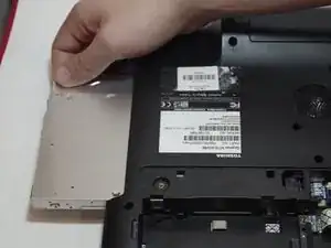
    • Using your finger or a spudger, push the optical drive out of its compartment so you can grab it.

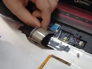
    • Pull the optical drive out of its slot in the side of the laptop.

  7. G36OjOsUmH5DExgP
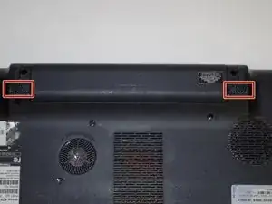
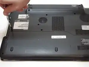
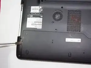
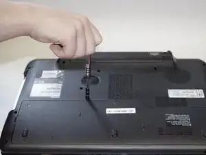
    • Loosen the single screw on the service panel by twisting counterclockwise with a Phillips #00 screwdriver.

    • It is a captive screw that will remain attached to the service panel.

  8. WG4BuG3m2uVX1anj
    • Using a spudger or plastic opening tool, pry off the service panel.

  9. sfew3Srniivjjf6y
    sfew3Srniivjjf6y
    BYVn1lrTYOMCxmuj
    UeCrJvrdYhuqwENY
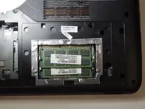
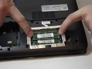
    • Using your fingers, pull the retaining clips away from the RAM sticks.

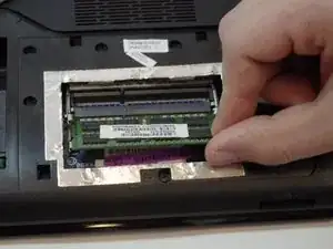
    • Pull the RAM sticks out of the slots.

  10. J1BgIvKoGOEqknRd
    J1BgIvKoGOEqknRd
    wywiawKJOagEJW5V
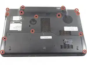
    • Using a Phillips #00 screwdriver, remove all the remaining fourteen screws from the bottom case of the laptop.

    • The service panel should already be removed.

  11. c66BBY2QXesD2Bjg
    c66BBY2QXesD2Bjg
    H5upORSs5HdIKvNE
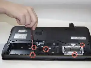
    • Using a Phillips #00 screwdriver, remove the five screws under the service panel.

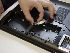
    • Remove the retaining clip.

  12. JbuUiJWlYr4QBSeR
    • Using a spudger, pry the keyboard from the top panel of the laptop.

    • Make sure to pry it off all around.

  13. OgRAePSdfITkZaWg
    OgRAePSdfITkZaWg
    dPJMPa24kEgYFBKt
    1FoEjHj2F1fgyAQu
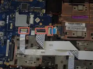
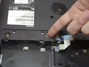
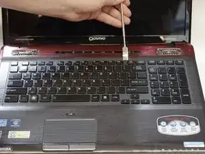
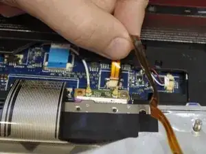
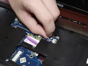
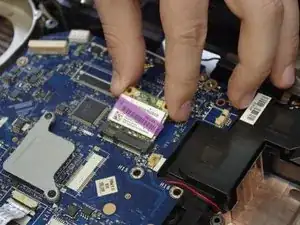
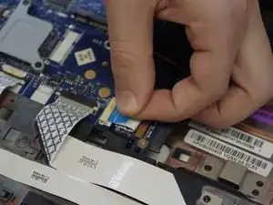
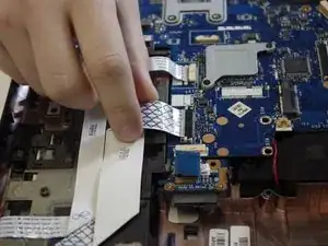
    • Disconnect the two ribbon cables connecting the keyboard to the laptop.

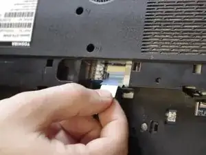
    • Unplug the connector on the bottom of the laptop.

  14. yCqyLPVp4YFLXeHd
    • Separate the two halves of the base of the laptop.

  15. WBZVNLYWtMOLZ4YO
    WBZVNLYWtMOLZ4YO
    TyRHfCQX133pqoUH
    • Disconnect the two cables.

  16. QRVOKGExuD2CFgCw
    • Remove the palmrest assembly.

  17. CvWoTXacgt5VAQbC
    CvWoTXacgt5VAQbC
    4T5DbYbHCIxTCLFG
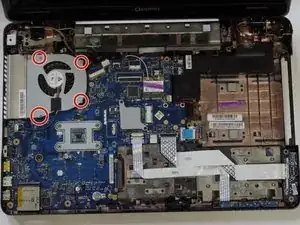
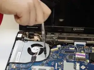
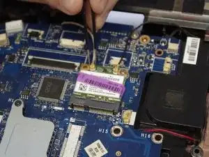
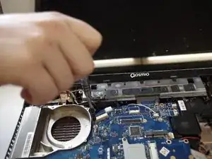
    • Using a Phillips #00 screwdriver, remove the four screws securing the fan assembly to the laptop.

  18. XiGE1OwwsUGgsJFZ
    XiGE1OwwsUGgsJFZ
    F43fErGvTLiuULj3
    • Unplug the fan-motherboard connector.

    • Remove the fan unit.

  19. gOfIwWFNLSqYhnAH
    • Detach the two coaxial connections from the wifi chip.

  20. E5JHLqw5OV2vPMHY
    E5JHLqw5OV2vPMHY
    vLgMZXaqL5HMkux2
    • Using a Phillips #00 screwdriver, remove the two screws from the wifi chip.

  21. PeMJLSrtOTGIMU5D
    • Remove the wifi chip by pulling it out of the PCIe slot.

  22. gSawYEYECsoOw4wO
    gSawYEYECsoOw4wO
    CTCTsWZxyqqVKbeb
    GCeJtC4cHucmg1cZ
    • Disconnect the three ribbon cables.

  23. WIOOUdFc2BaeduKh
    WIOOUdFc2BaeduKh
    s3LOEdOLLKs6VjVm
    OQKP1jvsYSJAXD4d
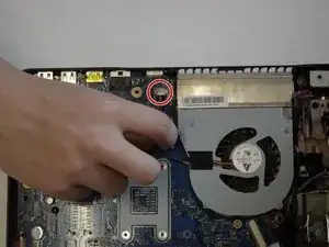
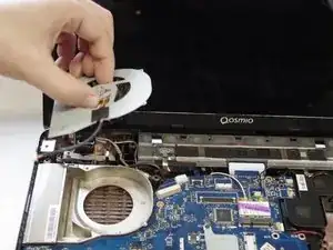
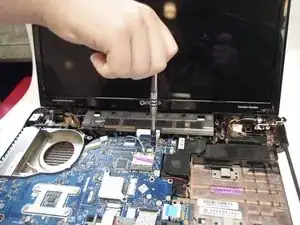
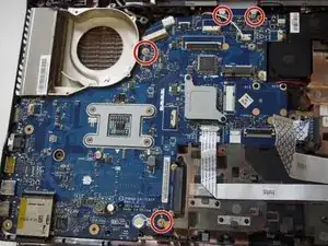
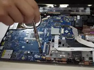
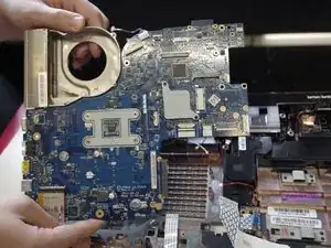
    • Using a Phillips #00 screwdriver, remove the four screws securing the motherboard to the laptop.

  24. SdVPKcRk3VYRdWyd
    • Disconnect the pinned connector.

  25. gGRMorMWnMDYHJFm
    • Remove the 4-pin connector housing by gently wiggling it back and forth.

  26. SDjL4qTsAGVmCD6i
    • Remove the motherboard.

Conclusion

To reassemble your device, follow these instructions in reverse order.

Jesse Adam Ory

Member since: 24/03/19

745 Reputation

0 comments