Introduction

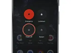
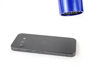
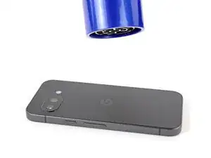
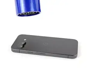
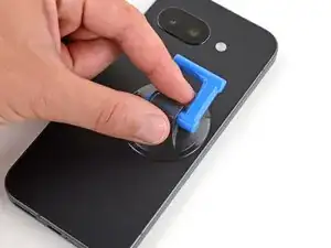
Prerequisite‑only guide for removing the suction handle and laying your Google Pixel 9a down.

  1. LTilkVoaHyOYJQoP
    LTilkVoaHyOYJQoP
    DDba2IYvihnIWjP6
    • Let your Pixel's battery drain below 25% before starting this repair. A charged lithium‑ion battery may catch fire if damaged.

    • Unplug all cables and completely power down your phone.

  2. bYF6ZtIlyRqfKWuk
    bYF6ZtIlyRqfKWuk
    2mviQoRt6YqIqT3Y
    Qq5KTYMxnUSumugx
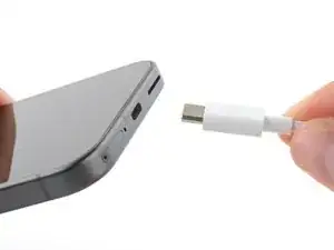
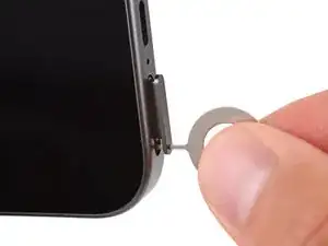
    • Firmly press a SIM eject tool, bit, or straightened paper clip into the SIM card tray hole on the bottom edge of your phone until the tray ejects.

    • A small mic hole is next to the SIM tray—don't confuse the two!

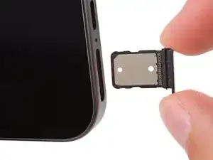
    • Remove the SIM card tray.

  3. CVGiiJOcueTmhWXd
    CVGiiJOcueTmhWXd
    Z4XDAGh4GjqZgDFq
    NpjsHAmlnLrQTWVK
    • Adhesive secures the rear cover to the frame. Heating the cover softens the adhesive, making it easier to separate.

    • Use a hair dryer to heat the entire rear cover.

    • Only heat your phone so it's just hot to the touch. Extreme heat can damage the rear cover, screen, or battery.

  4. J6pv6IchBtLPUasT
    J6pv6IchBtLPUasT
    TTFPI3y2na2vXKqq
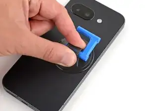
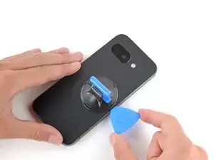
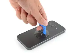
    • Apply a suction handle near the center of the rear cover's right edge, as close to the edge as possible.

  5. 4rVjh42ncYeqg6qZ
    4rVjh42ncYeqg6qZ
    6msJl2ioRDRyAZND
    PvutBItgXJu5TONB
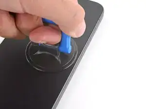
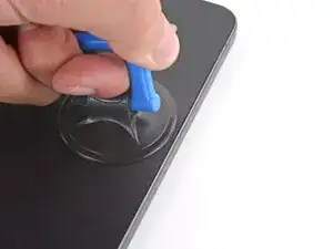
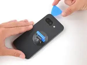
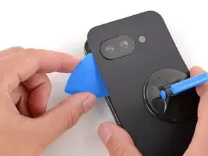
    • Pull up on the suction handle with strong, steady force until a gap forms between the cover and frame.

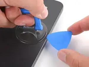
    • Insert the tip of an opening pick into the gap.

  6. 2tH2NaCWSHftGKme
    2tH2NaCWSHftGKme
    YmdtALiUKU2dU6vW
    1G64lYQaZmVchrKh
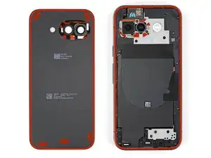
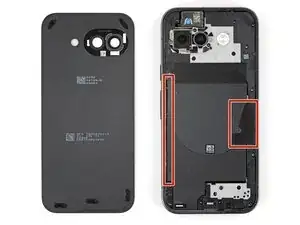
    • The rear cover is secured with adhesive around the perimeter of the frame and near the cameras. Use this picture as a reference while you separate the adhesive.

    • When separating the left and right edge adhesive, don't insert your pick more than 3 mm to avoid damaging the wireless charging coil and its graphite film.

  7. BEwtTXQygQAesTLu
    BEwtTXQygQAesTLu
    NKoSPZBACrlnJTQH
    UvHZJWMu6eYCLNAx
    • If you ever have trouble separating the adhesive, apply more heat and try again.

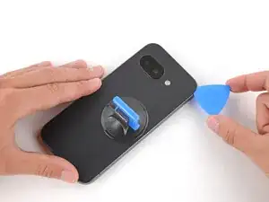
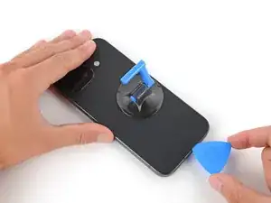
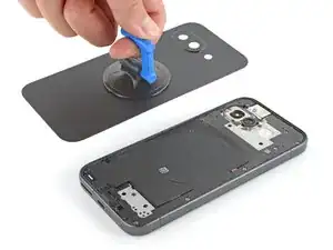
    • Slide the opening pick up the right edge, around the top right corner, and along the top edge to separate the adhesive securing the rear cover.

  8. dLBAllyMGHHPc6fR
    dLBAllyMGHHPc6fR
    5MqWaxsHMnIkYnXX
    XJJMBYQES5jdtkRH
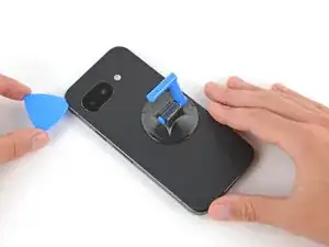
    • Insert an opening pick in the initial gap you created near the center of the rear cover's right edge.

    • Slide the opening pick down the right edge, along the bottom edge, and up the left edge to separate the adhesive securing the cover.

  9. VO6gYWioMLjWwCG1
    VO6gYWioMLjWwCG1
    NlKZGbytXIwpSNOD
    OyHTaZV46XrijmYR
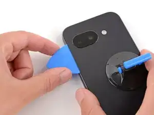
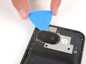
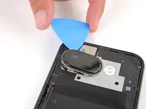
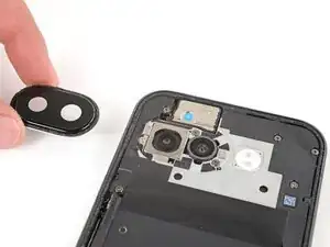
    • Insert the flat edge of an opening pick under the top of the rear cover's left edge, near the camera bezel.

    • Twist the pick and apply constant pressure to separate the adhesive around the camera bezel.

  10. YBO5nXARh3dlv4ip
    YBO5nXARh3dlv4ip
    YEQX31rsPPCwMVV1
    • Remove the rear cover.

    • If you feel resistance, go back around the perimeter of the cover and use a pick to separate any remaining adhesive.

  11. QmtFTp1MUvU5CwbT
    QmtFTp1MUvU5CwbT
    kWhMVBOfY6bPHPtp
    rsmvaPTO2wxULOAv
    • If the camera bezel detached from the rear cover and stayed stuck to your phone, follow this step to remove it. Otherwise, skip this step.

    • Slide an opening pick under the camera bezel and pry up to remove it.

    • Only insert the pick a few millimeters under the bezel, or you risk damaging the cameras.

    • If you're having trouble, lightly heat the camera bezel.

  12. cxYTwk6hrNocZOtu
    cxYTwk6hrNocZOtu
    vVCDHe2O1ZqcrIsA
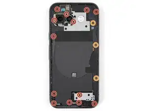
    • Use a Torx Plus 3IP screwdriver to remove the 16 screws securing the wireless charging assembly:

    • Thirteen 5.0 mm‑long screws

    • Three 2.2 mm‑long screws

    • Throughout this repair, keep track of each screw and make sure it goes back exactly where it came from to avoid damaging your phone.
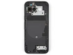
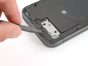
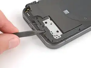
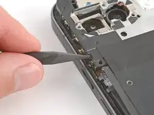
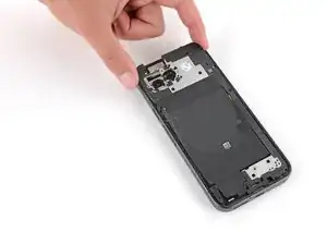
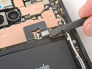
  13. InpP5tXaoYCBZgMG
    InpP5tXaoYCBZgMG
    alaIhxljPsvKA1fI
    Uh5G2UNLCGvEkEPE
  14. qvsd2Ns2xKLWLSbM
    qvsd2Ns2xKLWLSbM
    bd6wdAjqISIwLXum
    • Remove the wireless charging assembly.

  15. HfEWwNSGGULSQye4
    HfEWwNSGGULSQye4
    vCo5UZGjseailvOw
    • Be careful not to damage the battery with your tools while disconnecting it.

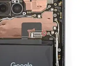
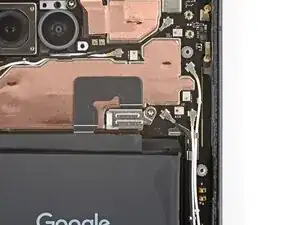
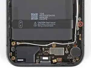
    • Use a Torx Plus 3IP screwdriver to remove the 1.7 mm‑long screw securing the battery connector cover.

  16. OHaFpoFnj2uTRQ2L
    OHaFpoFnj2uTRQ2L
    UuKAkY1WGAkJxDJM
    sLu6WxFTnJlRHTr6
    • Use tweezers to lift and remove the battery connector cover.

  17. fRFfxyRJKwjgQnLH
    fRFfxyRJKwjgQnLH
    6ZkibGEZ4wFOSxRM
    • Use a spudger to pry up and disconnect the battery cable press connector.

  18. wXGFURKDOZXxMVEY
    wXGFURKDOZXxMVEY
    V2KLoo2a4M1LMwEL
    ApAOuZMuVLRKvrIS
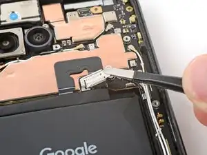
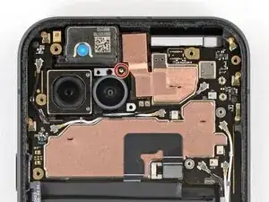
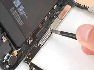
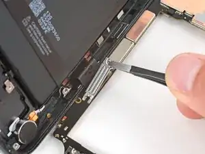
    • Use a 3IP Torx Plus screwdriver to remove the two 2.8 mm‑long screws securing the logic board.

  19. IEHGag5RDZwxVX3s
    IEHGag5RDZwxVX3s
    ij3KtwTYjnF3DVoe
    RywkTClFDWIGhhVb
    • Be careful not to smudge the cameras when handling the logic board.

    • Before trying to remove the logic board, double‑check that you removed the SIM card tray.

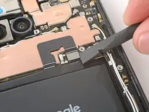
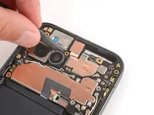
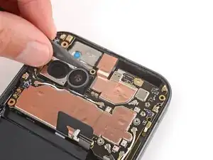
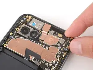
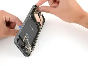
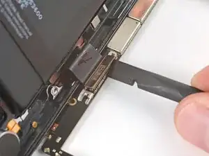
    • Insert the point of a spudger under the screw hole near the cameras and lift the board until you can grip it with your fingers.

  20. RqDY3xOgeMbCZCOy
    RqDY3xOgeMbCZCOy
    UOqN4PSsBiCOuyb6
    Q6E3GeWK4rJ2Yafu
    • Don't try to fully remove the logic board yet, as it's still connected to the frame by the screen cable.

    • Grip the skinny section of the board with your fingers and lift until the clip near the bottom edge of the battery releases.

    • Pull the top edge of the board to the right of the frame until the charge port slides fully out of its recess.

  21. daqvKMnRSKhSGxes
    daqvKMnRSKhSGxes
    Q5slAPvjxSK6gX4q
    vHk2aXskEXQiUjvK
    • The logic board may fall out of place during this step. Hold it steady, but don't grip any of the camera lenses or connectors.

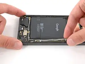
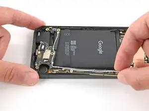
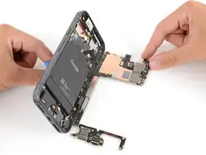
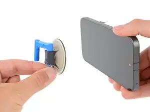
    • Apply a suction handle to the screen and use it to prop up your phone.

    • Gently lay the logic board down flat against your work surface, being careful not to strain the screen cable.

  22. PNGGG2QGHa6CVxNe
    PNGGG2QGHa6CVxNe
    HKGgb1Sefl5LkfLG
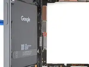
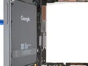
    • Use a Torx Plus 3IP screwdriver to remove the 1.7 mm‑long screw securing the screen cable cover.

  23. ZxBunBtHMmNp4UaX
    ZxBunBtHMmNp4UaX
    QtqMxahMEfUSi4Vl
    ycX6bYHIUKxGrPkP
    • Use tweezers to lift and remove the screen cable cover.

  24. CASMXZ12Be6LQEnM
    CASMXZ12Be6LQEnM
    WmQTg1oW3XEO1BIo
    • Use the flat end of a spudger to pry up and disconnect the screen cable press connector.

  25. 1jpehPYUsyQf2ylD
    1jpehPYUsyQf2ylD
    oagJCS22OQgKEXJW
    • Slide the logic board away from the frame and remove it.

  26. Ksa3vEyEif2cFOl5
    Ksa3vEyEif2cFOl5
    3ROF1qhOVP3Tf3Cs
    • Remove the suction handle from the screen and lay your phone down.

Spencer Day

Member since: 14/09/22

117606 Reputation

0 comments