Introduction

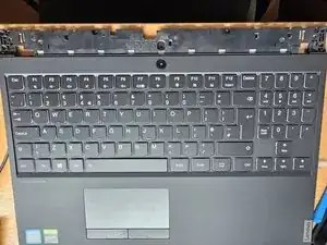
This guide describes and shows the procedure of replacing the upper case of the Lenovo Legion Y530-ICH. The upper case includes the keyboard, power button, touchpad and the top surface area surrounding those parts.

  1. fS1SmJyIjFsr1UxM
    fS1SmJyIjFsr1UxM
    XIybx1IaWPMakpYR
    UdSy6ZHsqFkEZluG
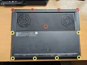
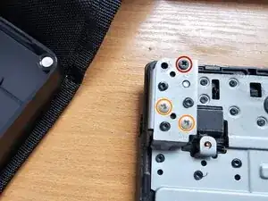
    • Remove 5 M2.0 × 8.0 mm screws

    • Remove 6 M2.0 × 4.0 mm screws

    • As you unscrew your way through this laptop, you will need an organizer for your screws. It helps me to sort them in chronological order, making reassembly easy by simply backtracking. Trust me, this is important!

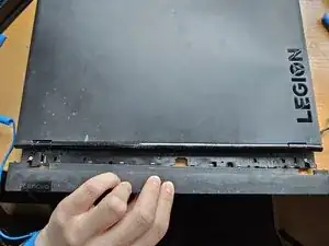
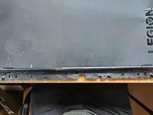
    • Remove the cover by lifting from the side closest to you. But be careful! On both left and right sides, next to the USB slots, you'll find it doesn't really budge. So insert an opening pick and pry a little bit, and it'll go smoothly once again.

  2. 4ZgDhFVTnhCRDxlB
    4ZgDhFVTnhCRDxlB
    tDTwrZi5CONNOOqq
    3r5OXc4UKgD1fvCi
    • Remove 5 M2.0 x 5.0 mm screws

    • Detach the battery connector by pulling it away from its slot.

    • Easiest way to do this is to grab both edges with your nails and pull, or use a spudger and shimmy it out by pushing left and right side repeatedly.

    • You can also lift the battery out first to have more room to pull the connector (the wires are quite compressed there). You can just pull by the set of wires, but do be careful and don't pull too hard, or else you'll have another problem on your side.

  3. NiTF4JSRiTGPoTSi
    NiTF4JSRiTGPoTSi
    fBbR2N36fHFfkNrZ
    Djs3sJvSOQQlsCsS
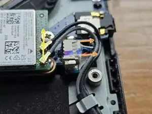
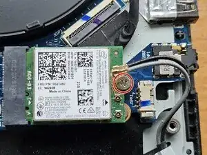
    • Disconnect the two (in my case, black and gray) wifi card cables by pulling them away from the wifi card.

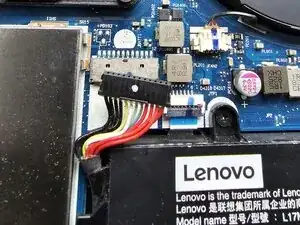
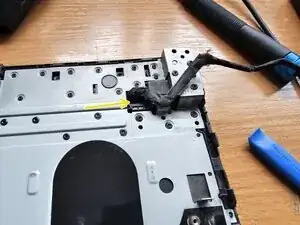
    • Disconnect the speaker cable by pulling its connector out of the socket, towards the right side

    • It requires a bit of force, but easiest would be to grab it with your fingernails on its left and right side and either shimmy it out or just pull. Try not to pull on the wires.

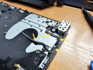
    • Detach the speaker wire from its metal holders. It is likely you will need to also move the wifi card wires, at least partly, to be able to do that.

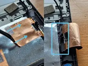
    • You will notice that you cannot move the speaker wire due to the copper sticker. Use your fingernails or opening tools to get it going and then carefully, but firmly pull it towards the right side, to free the way for the speaker wire.

    • As a final step, pull the speaker wire out of the holders beneath the copper sticker.

  4. ZrVZPJsnJ1yylT6T
    ZrVZPJsnJ1yylT6T
    QLVCYvCNUAbRKgRk
    PsysXkmyY2MkQfos
    • Remove 2 big M2.0 x 3.0 mm screws.

    • Remove the left and right parts of the speaker by pulling it up and out of the holder. Be careful not to lose the rubber rings!

    • There is a thin wire connecting the two parts. Be careful not to damage it.

  5. tSvES2aiKpWdAMGP
    tSvES2aiKpWdAMGP
    jS1L2uQGnFv5FxJD
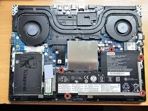
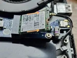
    • Remove 1 M2.0 x 3.0 mm screw

    • The wifi card will prop up at an angle. Do not panic, this is normal.

    • To remove the wifi card, hold it with two fingers on the sides and pull it in the diagonal direction it is facing when propped up on its own (around 30° by my estimation)

  6. Cq4mmgyoRGyQEljI
    Cq4mmgyoRGyQEljI
    BUpLvCZEHhHJGZK6
    HibotUWhGKTLdcJU
    • The heatsink assembly includes the heatsink through which fans blow, as well as the cooling pipes and copper contact points on the other side (for the CPU and GPU). It does not include the fans (those will be removed in a later step).

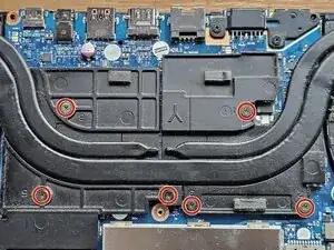
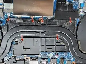
    • To start, loosen the 6 screws holding the heatsink pressed down. The numbers don't matter, these are for when you put the heatsink assembly back in.

    • These screws don't come out of their holes, they are meant to stay in.

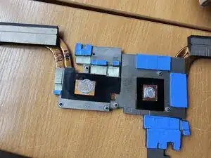
    • Once you're sure the screws are loosened, lift the heatsink assembly up and away from the laptop by holding it for its furthermost right and left ends. Be careful not to bend or damage anything. Place the heatsink assembly upside down.

    • You will notice the square and rectangle shaped contact points for cooling the GPU and CPU, respectively. They will be smudged by (most likely) old thermal paste. You will also notice these same shapes, smudged with thermal paste on the motherboard itself. These are your GPU and CPU.

    • This would be a good time to perform thermal paste clean up. Use your thermal paste cleaner or >90% isopropyl alcohol together with cotton swabs and cotton balls (or a microfiber cloth) to clean the thermal paste from all 4 surfaces.

    • Don't worry if there is some residue on the sides, thermal paste is made to be non-conductive, so your electrical components are safe.

  7. HLbagYc2jFT6yTYd
    HLbagYc2jFT6yTYd
    TMT2ddmXn5NlJ4Hh
    • Skip this step if you're disassembling the laptop. Perform this step when you're about to put the heatsink back into the laptop.

    • Apply a small amount (official guide says 0.2g) of thermal paste on each - CPU and GPU cooling contacts. CPU is longer, so apply a line, while applying a dot fits the GPU contact point better.

    • When putting the the heatsink back in, tighten the screws in the order written on the heatsink - from 1 to 6. You cannot overtigthen, as these screws simply stop at their designated torque level.

  8. qxDYNrEtSuLMlD6q
    qxDYNrEtSuLMlD6q
    qgoXICj2rvUJjhDq
    npfwNcMwjLxACC2j
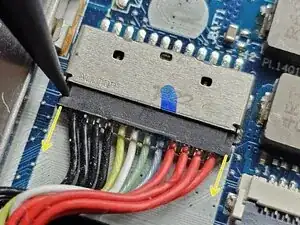
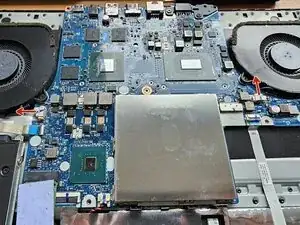
    • Unplug the fan connectors in the direction shown by the arrows. The connectors are similar to the speaker connector, so use the same method here.

    • Remove the 4 M2.0 x 5.0 mm screws

    • Lift the fans up and out of the laptop

    • At this point, you can perform fan and heatsink cleaning by using a paint brush with long bristles and/or compressed air. A soft, large brush will work well here and allow you to perfectly clean your fans. Be careful not to apply too much pressure to the fan blades, however.

  9. 35UBOcaOWFwARKTJ
    35UBOcaOWFwARKTJ
    KPpsSnN2cHYmxNmL
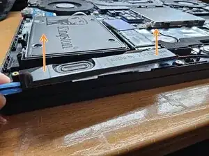
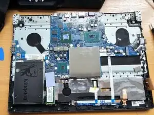
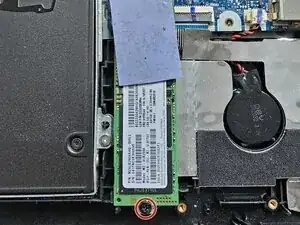
    • This is the same as when you removed the wifi card, unfasten the 1 M2.0 x 5.0 mm screw. The SSD will raise and stand at an angle.

    • Remove the SSD by holding it for its sides and lightly pulling in the diagional direction it is pointing at. It should come out easily.

  10. UZnjfogqEkIF1gBM
    UZnjfogqEkIF1gBM
    dGBPLWGmqrZKsLZB
    T4RcttlBgVjNgCTg
    • This slot usually comes empty, in which case you still must perform this step. The SATA disk holder in your laptop is what you'll be removing then, and the process is the same, save for unplugging the disk from the motherboard.

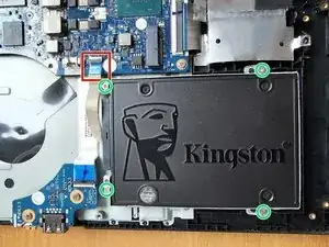
    • Unplug the motherboard connection to the the SATA disk. You can do this either by unplugging it via the ZIF connector or by removing the SATA connector. My ZIF connector came out on its own when putting the SATA drive back in, so I'd recommend doing that anyway. Lift the little black latch up and to the right (as far as it goes) and then pull the wire out.

    • Unfortunately, I do not have good pictures of me unplugging the wire from this connector. You can find out how to work with ZIF connectors by clicking on the link above, or in the following steps, as there are plenty more of these to be found.

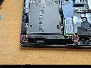
    • Unscrew the 4 M2.0 × 3.5 mm screws and lift the disk up and out of the laptop.

  11. GkC6luhFYRDeARJh
    GkC6luhFYRDeARJh
    PIeDGOsUIqwTbih4
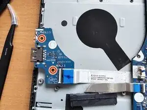
    • Unscrew the 2 M2.0 × 3.5 mm screws. Don't mind that I've already taken them amount (whoops, forgot to take a pic before).

    • Unstick the cable from the metal frame.

    • The cable connecting the IO board to the motherboard has some kind of glue connecting a part of it to the metal frame. To remove it, hold the cable (not the IO board) and pull with just enough force to slowly unstick it. Do it carefully.

    • If you want to, you can unplug the ZIF connector connecting the motherboard to the IO board, but it is absolutely not necessary for our purposes.

  12. UDMImWrJI1BKEQEx
    UDMImWrJI1BKEQEx
    uCSMh4f1UcYqY4VI
    kCQTmseFKyqe63OT
    • This is an important step, as it lowers the risk of any shorts happening while handling the motherboard.

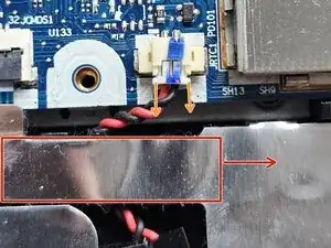
    • The connector for the RTC battery is similar to the speaker and fan connectors. Before removing it, lift the silver flap that's also stuck to a wide cable connected to the motherboard.

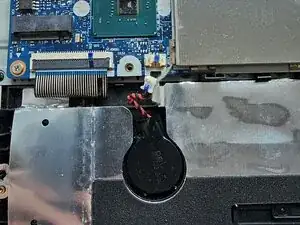
    • To unplug the battery, pull on the connector in the direction of the arrows. It is a similar connector to the speaker and fan connectors. In my case, it required a bit more effort to get it out.

    • Finally lift and unstick the battery from it's holder and put it aside.

  13. XfKiRMwufECORsWd
    XfKiRMwufECORsWd
    6UGLhXT4WVHSEJhL
    • Unscrew the 2 M2.0 × 5.0 mm screws and lift the bracket out.

  14. hfc3IOWiSgxcYXag
    hfc3IOWiSgxcYXag
    ZxKubHEHJXqqvCsM
    pfS52pkNtItRItse
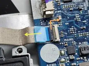
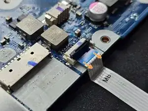
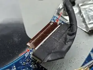
    • First, we must unplug the 2 ZIF connectors.

    • To unplug a ZIF connector, lift the black flap up and away as far as it goes. You can use your nails, an opening tool or anything else.

  15. X1DCSNRxpf3aup2F
    X1DCSNRxpf3aup2F
    QgKrIFSLTjm1hGx3
    jqAPhrZemrZHF4Nr
    • Then, use the tweezers or your fingers to gently pull the cable out. Grab the blue strip, as it is intended to be a helping tool when plugging and unplugging these cables. It should have no resistance.

    • Repeat the process with the other cable, but this time on the motherboard instead of the touchpad board. This one didn't have a big enough blue strip to grab with my tweezers, but it was easy enough to pull out without needing them.

    • When plugging ZIF connectors back in, push them in all the way and close the flap back down. Usually, there is a line indicating where the latch should rest while closed. Also keep in mind that in some cases, this line is just in front of the closed latch, and sometimes covered by it.

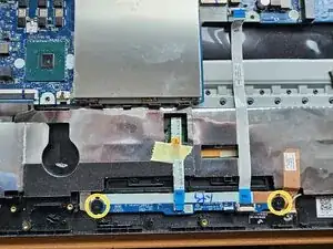
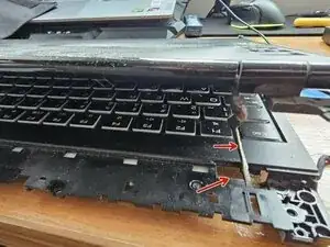
    • Finally, unscrew the 2 wide M2.0 × 3.0 mm screws and lift the touchpad board, along with one cable, out of the laptop.

  16. DcmaD6BQ6QQCJ6xX
    DcmaD6BQ6QQCJ6xX
    mgUMXntseOvgKRkO
    KNRUMG1qFImJuLXW
    • This is the trickiest part in this whole guide. Be careful not to damage or tear any cables or wires, or damage any components.

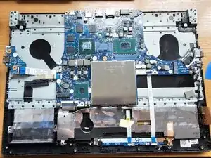
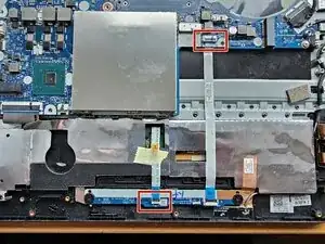
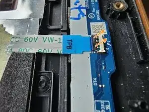
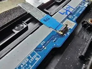
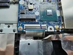
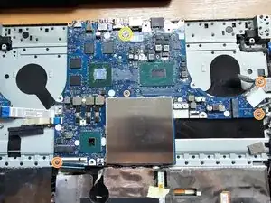
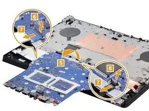
    • Detach the 2 ZIF connectors in the bottom left and right side of the motherboard. They are wider than others so they're easy to spot.

    • The connectors have flaps on the sides! I didn't know this at first and was confused why they didn't want to come out easily. You must lift them up and then out to detach them. When putting them back in, make sure the side flaps are securely inside of the connector.

  17. jGSfWhdhgjYHwhVZ
    jGSfWhdhgjYHwhVZ
    covSPNigDVfAW4Yf
    HBt53VI1U1TLXMHr
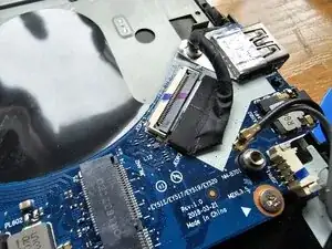
    • After deatching the connectors, unscrew the 3 M2.0 × 3.5 mm screws.

    • Unscrew 1 M2.0 × 5.0 mm screw, hidden behind a Lenovo sticker near the top of the board.

  18. 2RmUVF1hVa1dR6OW
    2RmUVF1hVa1dR6OW
    nCqKYNiFXihGJfV1
    HPkdOPNUNteYDklk
    • Flip the board over by lifting the part of the board furthest away from you and placing it on the laptop slowly so that you can see its underside. You will notice a cable which you must unplug. You can see what this looks like on the screenshot from the manual.

    • Once you've unplugged the connector, remove the entire board from the laptop.

  19. m1H3LEAMyGunA1d1
    m1H3LEAMyGunA1d1
    qBdCNmlJMhuF2Hyo
    Xgp2lPbRfplA5SPk
    • Remove 1 M2.5 × 7 mm black-coloured screw from one of the hinges.

    • Remove 2 M2.0 × 2.3 mm silver-coloured screws.

    • Repeat this process for the other hinge.

    • Free the black cable you disconnected earlier on the right side. It has a little bit of glue on one of its parts. This cable will come out through the hole that you can see.

  20. jqfMBETLiEJBPVZD
    jqfMBETLiEJBPVZD
    gLlOJEmEBrQplCDZ
    sPB6NFVABGYG1Vmc
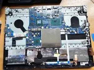
    • Flip the laptop the same way you flipped the motherboard earlier, being careful not to damage the cable you freed.

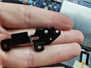
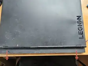
    • Pull the hinge cap up and then towards yourself diagonally to remove it. It should be easy.

  21. PCkOIHwEEPYh2uWK
    PCkOIHwEEPYh2uWK
    kJ462BU3EfZwGmix
    MPJxGXKKwRSMBfuI
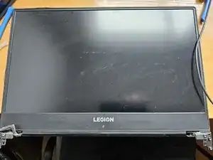
    • Pull the display up, being careful to route the black cable through the hole and then set it aside.

    • Congratulations!!! You successfully reached the end of this guide! Now it's up to you to take the new upper case unit and redo all these steps in reverse order. Be careful, as some things are a bit different, such as plugging the cables in instead of unplugging and applying thermal paste.

    • It was way less stressful for me putting things back together. I knew everything I've done so far so there was no unknown territory. Good luck and thank you for following my guide. :)

Conclusion

To reassemble your device, follow these instructions in reverse order. Don't forget to reapply thermal paste before putting the heatsink assembly back in. Don't rush and good luck :)

Dragoncat

Member since: 29/01/25

338 Reputation

0 comments