Introduction

This repair guide was authored by the iFixit staff and hasn’t been endorsed by Google. Learn more about our repair guides here.

Follow this guide to replace the earpiece speaker in your Google Pixel 9a.

If the sound during phone calls is crackly, distorted, or silent, your earpiece speaker may be damaged.

The gasket between the earpiece speaker and frame offers dust and water resistance, which may be compromised depending on the age and condition of your phone.

You'll need replacement rear cover and earpiece speaker adhesives to complete this repair. You may also need replacement logic board thermal pads if they get damaged during removal.

Note: Any repair can compromise the water resistance of your phone. Retaining water resistance after the repair depends on how accurately the new adhesives are applied and how clean the mating surfaces are.

  1. LTilkVoaHyOYJQoP
    LTilkVoaHyOYJQoP
    DDba2IYvihnIWjP6
    • Let your Pixel's battery drain below 25% before starting this repair. A charged lithium‑ion battery may catch fire if damaged.

    • Unplug all cables and completely power down your phone.

  2. bYF6ZtIlyRqfKWuk
    bYF6ZtIlyRqfKWuk
    2mviQoRt6YqIqT3Y
    Qq5KTYMxnUSumugx
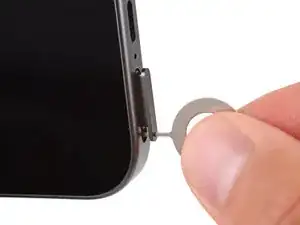
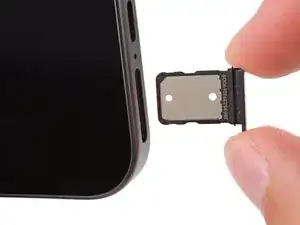
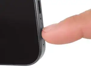
    • Firmly press a SIM eject tool, bit, or straightened paper clip into the SIM card tray hole on the bottom edge of your phone until the tray ejects.

    • A small mic hole is next to the SIM tray—don't confuse the two!

    • Remove the SIM card tray.

  3. CVGiiJOcueTmhWXd
    CVGiiJOcueTmhWXd
    Z4XDAGh4GjqZgDFq
    NpjsHAmlnLrQTWVK
    • Adhesive secures the rear cover to the frame. Heating the cover softens the adhesive, making it easier to separate.

    • Use a hair dryer to heat the entire rear cover.

    • Only heat your phone so it's just hot to the touch. Extreme heat can damage the rear cover, screen, or battery.

  4. J6pv6IchBtLPUasT
    J6pv6IchBtLPUasT
    TTFPI3y2na2vXKqq
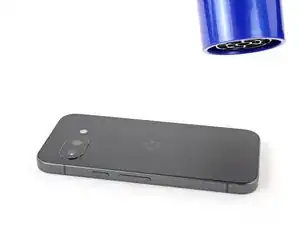
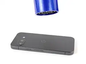
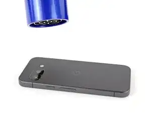
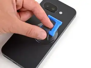
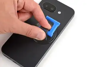
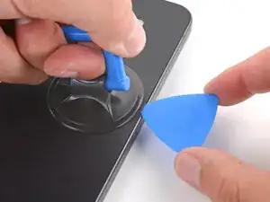
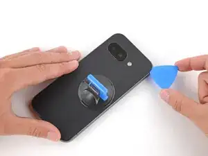
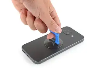
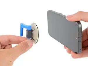
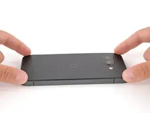
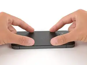
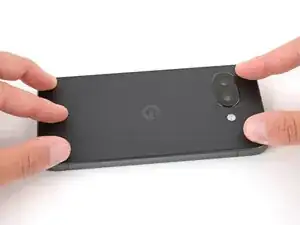
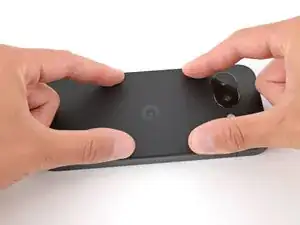
    • Apply a suction handle near the center of the rear cover's right edge, as close to the edge as possible.

  5. 4rVjh42ncYeqg6qZ
    4rVjh42ncYeqg6qZ
    6msJl2ioRDRyAZND
    PvutBItgXJu5TONB
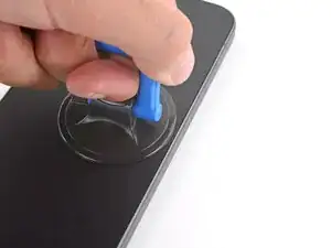
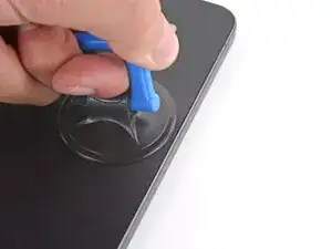
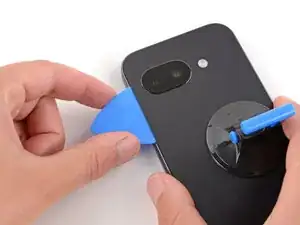
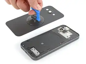
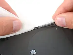
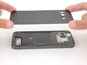
    • Pull up on the suction handle with strong, steady force until a gap forms between the cover and frame.

    • Insert the tip of an opening pick into the gap.

  6. 2tH2NaCWSHftGKme
    2tH2NaCWSHftGKme
    YmdtALiUKU2dU6vW
    1G64lYQaZmVchrKh
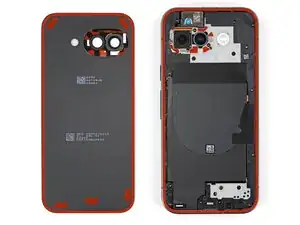
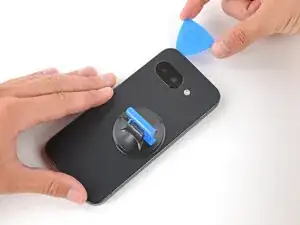
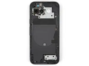
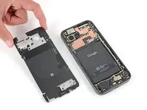
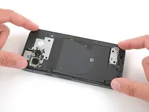
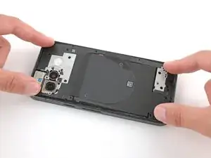
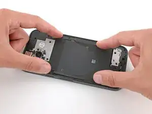
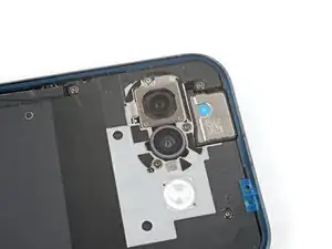
    • The rear cover is secured with adhesive around the perimeter of the frame and near the cameras. Use this picture as a reference while you separate the adhesive.

    • When separating the left and right edge adhesive, don't insert your pick more than 3 mm to avoid damaging the wireless charging coil and its graphite film.

  7. BEwtTXQygQAesTLu
    BEwtTXQygQAesTLu
    NKoSPZBACrlnJTQH
    UvHZJWMu6eYCLNAx
    • If you ever have trouble separating the adhesive, apply more heat and try again.

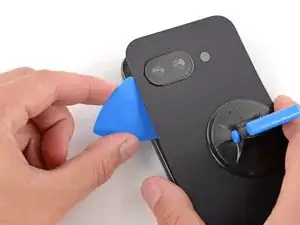
    • Slide the opening pick up the right edge, around the top right corner, and along the top edge to separate the adhesive securing the rear cover.

  8. dLBAllyMGHHPc6fR
    dLBAllyMGHHPc6fR
    5MqWaxsHMnIkYnXX
    XJJMBYQES5jdtkRH
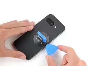
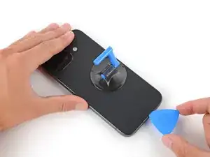
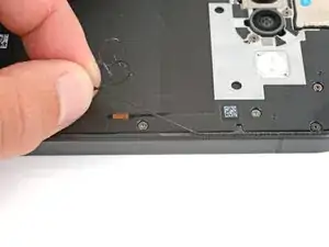
    • Insert an opening pick in the initial gap you created near the center of the rear cover's right edge.

    • Slide the opening pick down the right edge, along the bottom edge, and up the left edge to separate the adhesive securing the cover.

  9. VO6gYWioMLjWwCG1
    VO6gYWioMLjWwCG1
    NlKZGbytXIwpSNOD
    OyHTaZV46XrijmYR
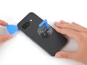
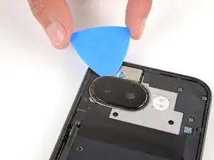
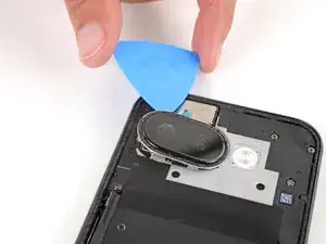
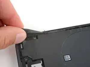
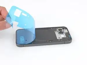
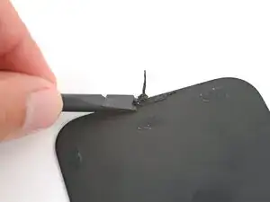
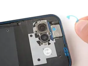
    • Insert the flat edge of an opening pick under the top of the rear cover's left edge, near the camera bezel.

    • Twist the pick and apply constant pressure to separate the adhesive around the camera bezel.

  10. YBO5nXARh3dlv4ip
    YBO5nXARh3dlv4ip
    YEQX31rsPPCwMVV1
    • Remove the rear cover.

    • If you feel resistance, go back around the perimeter of the cover and use a pick to separate any remaining adhesive.

  11. QmtFTp1MUvU5CwbT
    QmtFTp1MUvU5CwbT
    kWhMVBOfY6bPHPtp
    rsmvaPTO2wxULOAv
    • If the camera bezel detached from the rear cover and stayed stuck to your phone, follow this step to remove it. Otherwise, skip this step.

    • Slide an opening pick under the camera bezel and pry up to remove it.

    • Only insert the pick a few millimeters under the bezel, or you risk damaging the cameras.

    • If you're having trouble, lightly heat the camera bezel.

  12. cxYTwk6hrNocZOtu
    cxYTwk6hrNocZOtu
    vVCDHe2O1ZqcrIsA
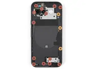
    • Use a Torx Plus 3IP screwdriver to remove the 16 screws securing the wireless charging assembly:

    • Thirteen 5.0 mm‑long screws

    • Three 2.2 mm‑long screws

    • Throughout this repair, keep track of each screw and make sure it goes back exactly where it came from to avoid damaging your phone.
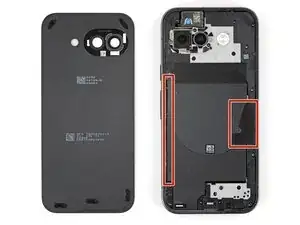
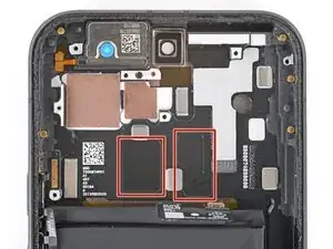
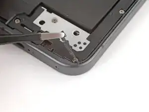
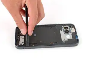
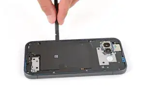
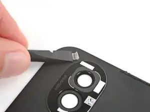
  13. InpP5tXaoYCBZgMG
    InpP5tXaoYCBZgMG
    alaIhxljPsvKA1fI
    Uh5G2UNLCGvEkEPE
  14. qvsd2Ns2xKLWLSbM
    qvsd2Ns2xKLWLSbM
    bd6wdAjqISIwLXum
    • Remove the wireless charging assembly.

  15. HfEWwNSGGULSQye4
    HfEWwNSGGULSQye4
    vCo5UZGjseailvOw
    • Be careful not to damage the battery with your tools while disconnecting it.

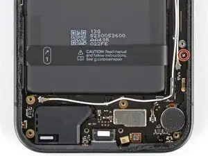
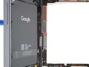
    • Use a Torx Plus 3IP screwdriver to remove the 1.7 mm‑long screw securing the battery connector cover.

  16. OHaFpoFnj2uTRQ2L
    OHaFpoFnj2uTRQ2L
    UuKAkY1WGAkJxDJM
    sLu6WxFTnJlRHTr6
    • Use tweezers to lift and remove the battery connector cover.

  17. fRFfxyRJKwjgQnLH
    fRFfxyRJKwjgQnLH
    6ZkibGEZ4wFOSxRM
    • Use a spudger to pry up and disconnect the battery cable press connector.

  18. wXGFURKDOZXxMVEY
    wXGFURKDOZXxMVEY
    V2KLoo2a4M1LMwEL
    ApAOuZMuVLRKvrIS
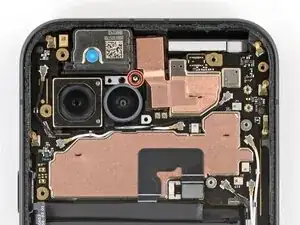
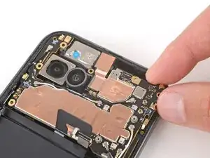
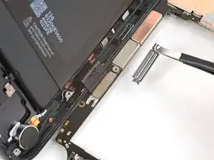
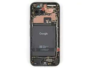
    • Use a 3IP Torx Plus screwdriver to remove the two 2.8 mm‑long screws securing the logic board.

  19. IEHGag5RDZwxVX3s
    IEHGag5RDZwxVX3s
    ij3KtwTYjnF3DVoe
    RywkTClFDWIGhhVb
    • Be careful not to smudge the cameras when handling the logic board.

    • Before trying to remove the logic board, double‑check that you removed the SIM card tray.

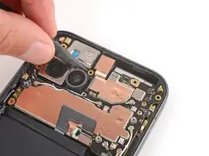
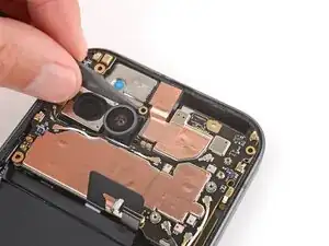
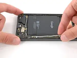
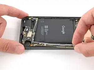
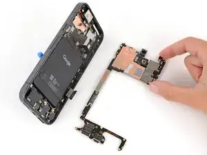
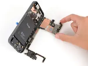
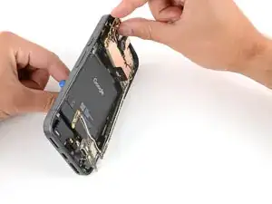
    • Insert the point of a spudger under the screw hole near the cameras and lift the board until you can grip it with your fingers.

  20. RqDY3xOgeMbCZCOy
    RqDY3xOgeMbCZCOy
    UOqN4PSsBiCOuyb6
    Q6E3GeWK4rJ2Yafu
    • Don't try to fully remove the logic board yet, as it's still connected to the frame by the screen cable.

    • Grip the skinny section of the board with your fingers and lift until the clip near the bottom edge of the battery releases.

    • Pull the top edge of the board to the right of the frame until the charge port slides fully out of its recess.

  21. daqvKMnRSKhSGxes
    daqvKMnRSKhSGxes
    Q5slAPvjxSK6gX4q
    vHk2aXskEXQiUjvK
    • The logic board may fall out of place during this step. Hold it steady, but don't grip any of the camera lenses or connectors.

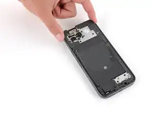
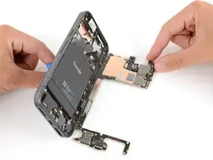
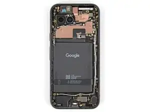
    • Apply a suction handle to the screen and use it to prop up your phone.

    • Gently lay the logic board down flat against your work surface, being careful not to strain the screen cable.

  22. PNGGG2QGHa6CVxNe
    PNGGG2QGHa6CVxNe
    HKGgb1Sefl5LkfLG
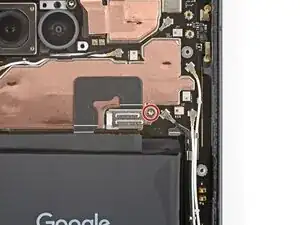
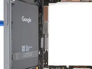
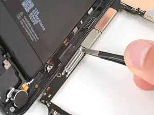
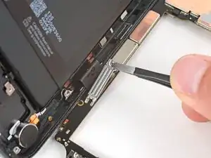
    • Use a Torx Plus 3IP screwdriver to remove the 1.7 mm‑long screw securing the screen cable cover.

  23. ZxBunBtHMmNp4UaX
    ZxBunBtHMmNp4UaX
    QtqMxahMEfUSi4Vl
    ycX6bYHIUKxGrPkP
    • Use tweezers to lift and remove the screen cable cover.

  24. CASMXZ12Be6LQEnM
    CASMXZ12Be6LQEnM
    WmQTg1oW3XEO1BIo
    • Use the flat end of a spudger to pry up and disconnect the screen cable press connector.

  25. 1jpehPYUsyQf2ylD
    1jpehPYUsyQf2ylD
    oagJCS22OQgKEXJW
    • Slide the logic board away from the frame and remove it.

  26. Ksa3vEyEif2cFOl5
    Ksa3vEyEif2cFOl5
    3ROF1qhOVP3Tf3Cs
    • Remove the suction handle from the screen and lay your phone down.

  27. nNsBFnayUYdRN1oA
    nNsBFnayUYdRN1oA
    vYAJKJXJHvAX6KNQ
    ILoj4r1PJUh6aIch
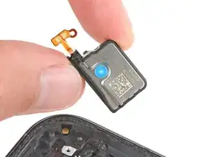
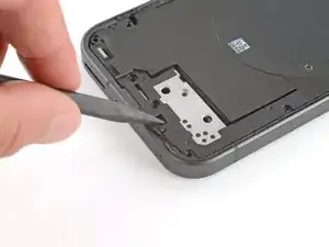
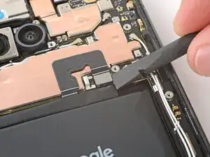
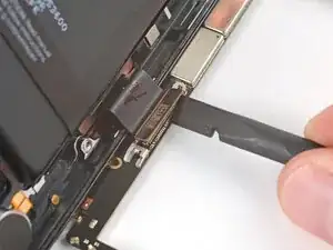
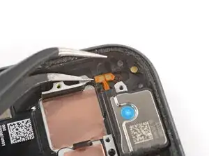
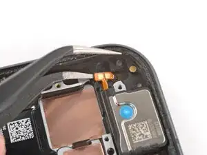
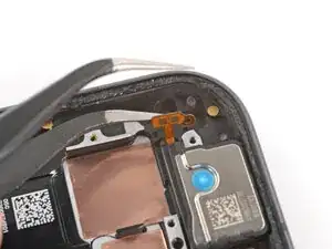
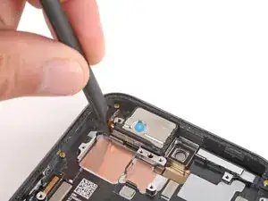
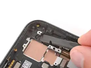
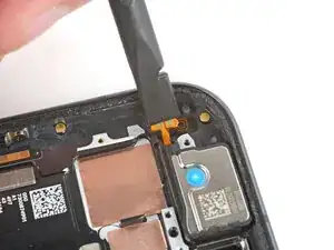
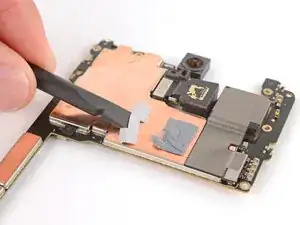
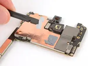
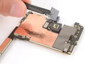
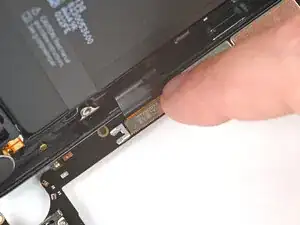
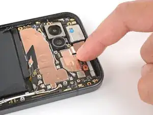
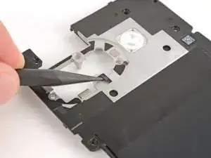
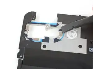
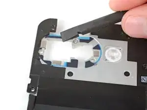
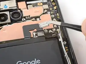
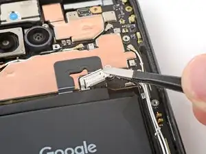
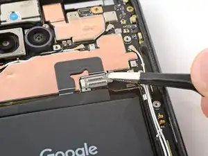
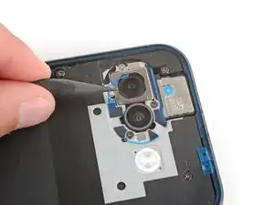
    • Slide one arm of a pair of angled tweezers under the earpiece speaker cable and lift to peel it off of the frame.

  28. hTJavoFUaUtlWrvK
    hTJavoFUaUtlWrvK
    PIg1UC52RP6rts4m
    oUctUnMVPI4Yljmb
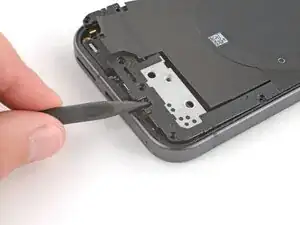
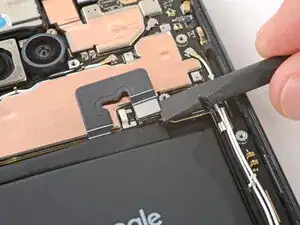
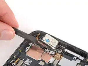
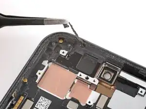
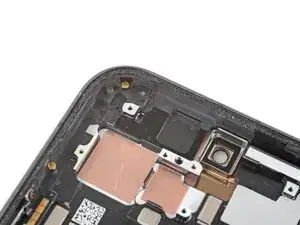
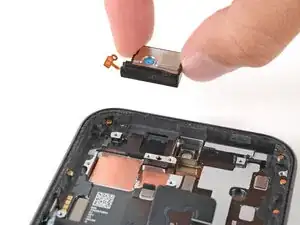
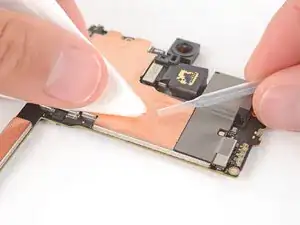
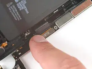
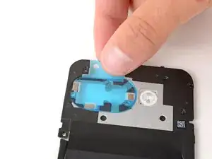
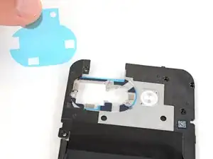
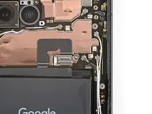
    • Use the flat end of a spudger to pry up the earpiece speaker by its left edge.

    • Adhesive secures the speaker to the frame, so this may take some force.

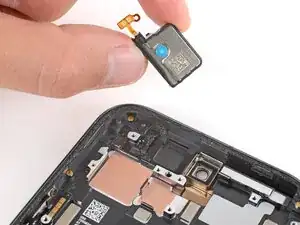
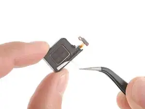
    • Remove the earpiece speaker.

  29. UcuSMoaAA3oG3YgP
    • Congratulations on completing disassembly! The remaining steps will show how to reassemble your phone.

  30. 3nrQwvETT1IvSL5L
    3nrQwvETT1IvSL5L
    W53THHxXQSxlScBV
    6KE32Hf6UYlKYiUh
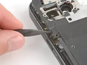
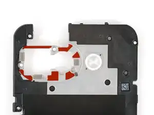
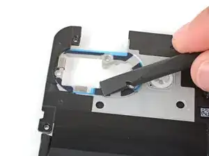
    • Use the flat end of a spudger and tweezers to scrape up and remove the old earpiece speaker adhesive from the frame.

  31. j3mJtNeRrDQEvPbh
  32. wJFH2xdSpbUUXpKA
    wJFH2xdSpbUUXpKA
    Vhnph6IUGssefaK1
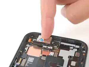
    • Set the earpiece speaker into its cutout (with the cable on the left) and press down firmly until it clicks into place.

  33. 6TJ1HZ2OVTGiBNpy
    6TJ1HZ2OVTGiBNpy
    I1y6sq4SNAIQTgOD
    K5eamn6IGRvArD4P
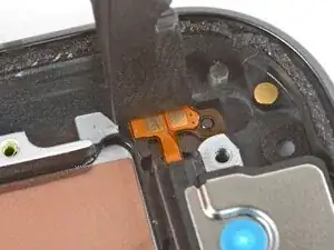
    • Use the flat end of a spudger to press the earpiece speaker cable into place on the frame, making sure the circular cutout goes over its alignment post.

  34. 2At2mUHYuSmkDtNf
    2At2mUHYuSmkDtNf
    VqEBQvaLVgLEhaYs
    • Check the condition of the logic board thermal pads—they'll either be on the bottom of the board or stuck to the corresponding spot on the frame.

    • If the pads are ripped, torn, or otherwise damaged, follow the next five steps to replace them. If they aren't, skip ahead five steps.

  35. fV62rqWCucH2GVDc
    fV62rqWCucH2GVDc
    C6UMXBBRTrwUbsGu
    PNywPNxWAqxJZHRv
    • Use the flat end of a spudger to scrape up and remove the damaged thermal pads.

  36. 2xbK3GdSVoxbwjXr
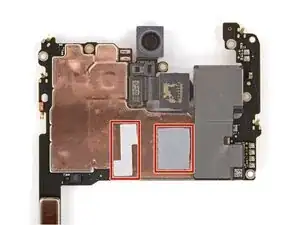
    • Use high‑concentration (>90%) isopropyl alcohol and a coffee filter to clean up and remove any residue where the thermal pads were.

  37. FfNrQMijLeeI32R5
    FfNrQMijLeeI32R5
    hEAhxpgmatB3Y5Hj
    daBfcrgctPQeKRO6
    • The thermal pads are very delicate and can easily be misaligned when placing them and removing liners. Take your time when applying them—good placement will ensure proper heat dissipation.

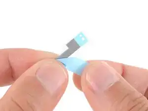
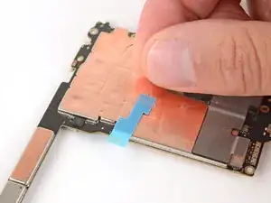
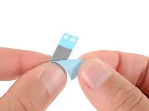
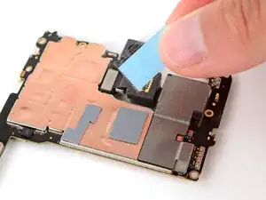
    • Remove the textured liner from the smaller thermal pad.

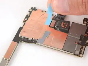
    • Carefully place the pad onto the board.

    • Use this photo as a reference to help align the pad.

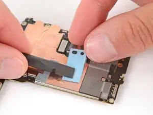
    • Use the flat end of a spudger or your finger to press down lightly on the entire surface of the thermal pad, securing it in place without deforming it.

  38. eXHbbtRVOskONyYr
    eXHbbtRVOskONyYr
    OErT4bFPtZmsscFk
    • Slowly lift and remove the remaining liners from the top of the thermal pad.

    • If the thermal pad start to lift up with the liners, lay it back down and press again to secure it.

  39. WWMMdBkFTyyjBRvw
    WWMMdBkFTyyjBRvw
    mrbWBGb44ceZW1rM
    xRT3OgQWZYSYDNUB
    • Repeat the previous two steps to apply the remaining, larger thermal pad.

    • Use this photo as a reference to help align the pad.

  40. JHoDHmVNHjGZyoOB
    JHoDHmVNHjGZyoOB
    VN1iIXf6VlTp5Eak
    • If it isn't already, prop your phone up with the suction handle.

    • Slide the logic board up against the frame so the screen cable is near its connector.

  41. YXJDiFaxThxGjECj
    YXJDiFaxThxGjECj
    53NZeCBACMmBNTUu
    yYoCmOPaXG4ABjEP
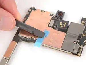
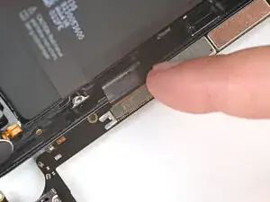
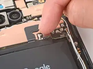
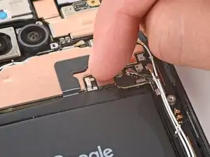
    • Align the screen cable press connector over its socket and press down with your fingertip—first on one side, then the other—until it clicks into place.

  42. XUgwGMrVS2IfnqxS
    XUgwGMrVS2IfnqxS
    BaekCjMyT5adHiON
    XHcH1DDH5gAydKmr
    • Use tweezers to hook the bottom edge of the screen cable cover into place, then lay the cover down flat.

  43. DtrWyTjSLeE6HP5v
    DtrWyTjSLeE6HP5v
    KiL6LeJOSnsUUuQj
    • Use a 3IP Torx Plus screwdriver to install the 1.7 mm‑long screw securing the screen cable cover.

  44. eEXcePfGplSf4Xkc
    eEXcePfGplSf4Xkc
    Mxq1HGTqjs3Tr4QP
    UYJCpZmhsWYy2hZ4
    • Be careful not to smudge the cameras when handling the logic board.

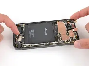
    • Flip the logic board up so it's gently resting in its recess in the frame.

    • Remove the suction cup and lay your phone screen-side down.

  45. iDNYyKGPBmW4ZEfF
    iDNYyKGPBmW4ZEfF
    LQNLhB6mMvisaJZ5
    gsZbFHvJLM1OJqLt
    • When inserting the logic board, make sure the battery cable doesn't get caught underneath. You may need to gently bend it out of the way.

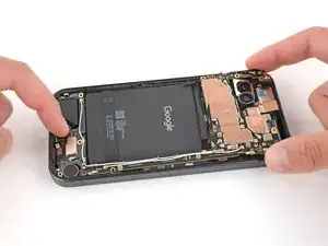
    • Push the logic board toward the bottom of the frame and press the charging port down until it snaps into its cutout.

    • Press down on the center of the logic board's bottom edge until the clip near the battery engages.

  46. cVwaIATlZPbVPlqE
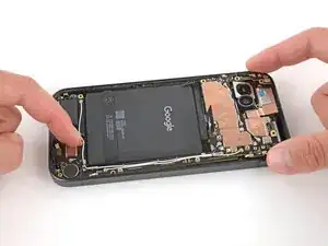
    • Push down on the top edge of the logic board so it goes into its recess. Make sure the cameras are sitting flush and not at odd angles.

  47. 3YOTuquNyAhVwvWm
    3YOTuquNyAhVwvWm
    5WyGBaafXlZQMeRO
    • Use a 3IP Torx Plus screwdriver to install the two 2.8 mm‑long screws securing the logic board.

    • Make sure the logic board lays flat, with nothing caught underneath, before tightening these screws.

  48. ecNEJPVyamPTYIMG
    ecNEJPVyamPTYIMG
    JETeRyYAFniyiwYQ
    • Use a spudger to scrape up and remove the six small pieces of adhesive around the rear cameras.

    • Use high‑concentration (>90%) isopropyl alcohol and a lint‑free cloth (or coffee filter) to clean up and remove any residue from the adhesives that were removed.

  49. Nxg6MgBrnQCD3GTO
    Nxg6MgBrnQCD3GTO
    SUHpXbjj1wrEx6Ml
    b66cLc2KCt1olvYf
    • Remove the larger, clear liner from the inner housing adhesive and lay it in place around the camera holes.

    • Use the cutouts for the small silver pads to help align the adhesive.

    • Use the flat end of a spudger to firmly push down on each piece of adhesive, securing them in place.

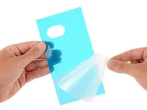
    • Remove the colored liner using the pull tab on the top edge.

    • If the adhesive starts to pull up with the liner, lay it back in place and use your spudger to secure it again.

  50. RCJCAhqx4hDdTIhh
    RCJCAhqx4hDdTIhh
    6fmeg3IjxdRFoT35
    v6VZ1sHfLDQuS4Cn
    • Use a spudger to firmly press down on each of the six pieces of inner housing adhesive to secure them.

    • These pieces of adhesive can easily be pulled up when removing the final liners, so make sure they're firmly in place.

  51. k4JQmHDGNAg5FCNo
    k4JQmHDGNAg5FCNo
    NdTPhA4YfcOjKR2g
    • Use your finger to align the battery press connector over its socket and press down to connect it.

    • Don't try to force the connector into place. If you're having trouble, reposition it and try again.

  52. S3iRGmRXma3C6qnf
    S3iRGmRXma3C6qnf
    gEkd4dXZWCPlJNwn
    qWExHM4lA1bKUVxw
    • Use tweezers to hook the left edge of the battery connector cover into place, then lay the cover down flat.

  53. 2qZRWjL2lHsS2LNy
    2qZRWjL2lHsS2LNy
    NImLTG3pvNdFr2OZ
    • Use a 3IP Torx Plus screwdriver to install the 1.7 mm‑long screw securing the battery connector cover.

  54. wDNoQwWaOimkn4jd
    wDNoQwWaOimkn4jd
    TgURpbRNUWNkYXP2
    • Place the wireless charging assembly onto the frame.

  55. MD1p3ZcQuVVYu4It
    MD1p3ZcQuVVYu4It
    FvvXxp3oqW2rPnoG
    pG3akVPrnwZcXBJF
    • Use your fingers to firmly press around the perimeter of the wireless charging assembly to re‑engage all of its clips.

  56. 4vTncwN5jGrRscWf
    4vTncwN5jGrRscWf
    ggTHX3EIHEsmWKQ4
    • Use a Torx Plus 3IP screwdriver to install the 16 screws securing the wireless charging assembly:

    • Thirteen 5.0 mm‑long screws

    • Three 2.2 mm‑long screws

  57. oK2P1gGqZtKBFpXm
    oK2P1gGqZtKBFpXm
    RCUToSt1F1mJluua
    kTlWb5GSeMhHNGrK
    • Take your time during the next two steps. A clean frame allows replacement adhesive to lay evenly, ensuring a better bond.

    • Use a spudger and tweezers to scrape up and remove all the old rear cover adhesive from the perimeter of your phone.

    • If you scrape up a piece big enough to grip with your fingers, you can pull long sections of the adhesive up. Pull slowly and straight in the opposite direction of the adhesive.

  58. ZF1ZETVgNWFqJesP
    • Using some high-concentration (>90%) isopropyl alcohol and a lint‑free cloth (or coffee filter), clean the areas of the frame where the adhesive was.

  59. csm6qkEIkbRHN2K4
    csm6qkEIkbRHN2K4
    H1MjWB15BRQsRUef
    • Before applying the rear cover adhesive, make sure you know how it will sit on the frame. If you apply the adhesive incorrectly, you'll need to restart with new adhesive.

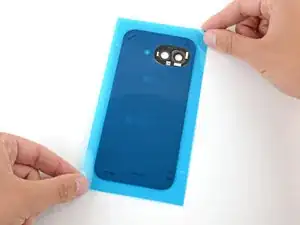
    • Hold the adhesive above the frame to find its orientation. Use the camera cutout in the liner to help visualize how it will lay on the frame.

  60. BPTYPMvxtMVis6TO
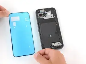
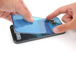
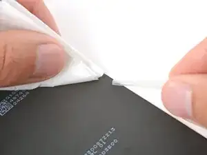
    • Peel down the top half of the large, clear liner to expose the adhesive—don't fully remove the liner yet.

  61. SepQQd2QtMkALBrJ
    SepQQd2QtMkALBrJ
    m2ScbLZGJ6mwtNZE
    xIAfx3TLTUoWHStC
    • Take your time aligning the adhesive with the frame—it's very sticky and can't be moved once you apply it.

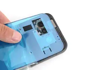
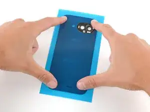
    • With the larger, clear liner folded towards the bottom of the phone, lay the exposed top edge of the adhesive onto the frame.

    • Use the lip of the frame to help align the adhesive.

    • Once the top edge is properly aligned, gently press down on the top corners with your fingers to secure the adhesive.

  62. BHcaLb2WNFqbVwQi
    BHcaLb2WNFqbVwQi
    YgJgtF5nXDHb1n2p
    EFl4GNdCNX1ZjjPD
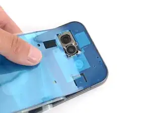
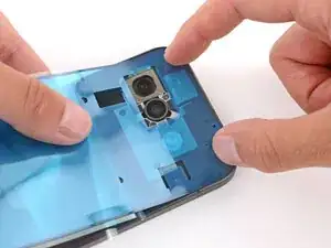
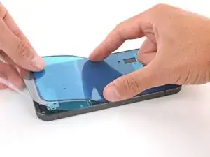
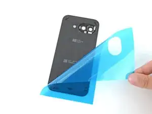
    • Slowly lay the rest of the adhesive onto the frame, pressing it into place and peeling away the larger liner as you go.

  63. WRtRWujAuy5LGg1I
    WRtRWujAuy5LGg1I
    M4ZsJnXddmQWcrLU
    qVJ4BcdHUkDw2Q5X
    • Use the pull tab to remove the large, colored liner.

  64. SjovbqHIoQnJAMob
    SjovbqHIoQnJAMob
    VWSJQxZWjgGA2DhO
    VZCJ6PCPfNmCvLbv
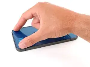
    • Use a spudger to press down firmly on the adhesive around the perimeter of your phone to secure it to the frame.

  65. 2m5pYdO2tjD5FDAx
    2m5pYdO2tjD5FDAx
    gb6usDIaA4EDXPAS
    • If the camera bezel detached when removing the rear cover, follow the next five steps to install it. Otherwise, skip down five steps.

    • Use a spudger to scrape up and remove any of the old adhesive from the camera bezel and its corresponding spot on the rear cover.

  66. WdEkJDFVeMOXwubP
    WdEkJDFVeMOXwubP
    fOmG4ZCuDbEQjYns
    • Use high-concentration (>90%) isopropyl alcohol and a lint‑free cloth (or coffee filter) to clean up and remove any adhesive residue from the camera bezel and its corresponding spot on the rear cover.

  67. jLZija5avNBmYueL
    jLZija5avNBmYueL
    P6EogYAVMITnnbB6
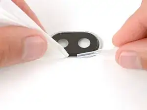
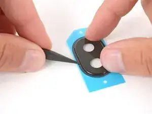
    • Remove the large, clear liner from the camera bezel adhesive.

    • Put the adhesive over the top of the camera bezel and set it in place.

  68. DPXhkoLhdJgUVBPb
    DPXhkoLhdJgUVBPb
    ShUbCAWlmtWqR6uI
    QlMNgei6X5lZySBU
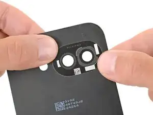
    • Use a spudger to firmly press around the perimeter of the camera bezel to secure the adhesive.

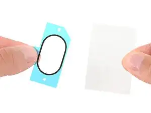
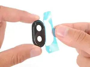
    • Remove the second, colored liner from the camera bezel adhesive.

  69. MgUgjxJJVodRVhpE
    MgUgjxJJVodRVhpE
    JdMfJgYUpLpcTEcr
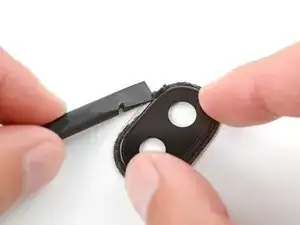
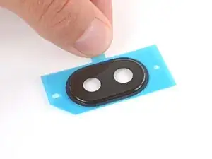
    • Align the camera bezel such that the square foam is closest to the edge.

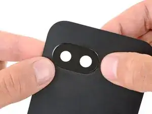
    • Use your fingers to press the camera bezel into place on the rear cover, squeezing firmly around the perimeter to secure it with the adhesive.

  70. CStPTSRXHX1sUqWc
    CStPTSRXHX1sUqWc
    jnMGY6kuOFMelRH3
    • Use the flat end of a spudger to scrape up and remove any all the old adhesive that stayed on the back cover, including the five pieces of small, oval‑shaped adhesive.

    • If you don't see all the oval adhesives, some might've stuck to the phone frame.

  71. kwYxH2YgaPvmZduK
    • Use high‑concentration (>90%) isopropyl alcohol and a lint‑free cloth (or coffee filter) to clean up and remove any residue from the adhesives you removed.

  72. nN24V1kN2ciBMhtM
    nN24V1kN2ciBMhtM
    iSBuF2EfsGB3I2TG
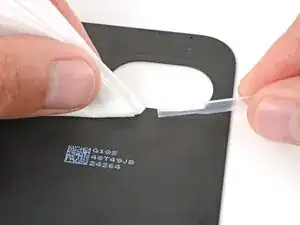
    • Remove the larger, clear liner from the back cover inner adhesive.

    • Lay the adhesive onto the bottom of the back cover, making sure the cutout goes around the camera bezel.

  73. RSraMRVelln5pNBR
    RSraMRVelln5pNBR
    ZfO2aiJPo3ImqABh
    • Use your fingers or a spudger to firmly push down on the five small adhesives to secure them to the back cover.

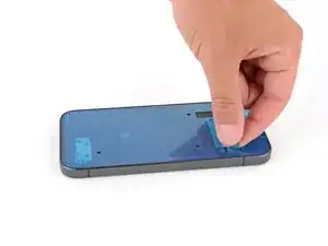
    • Slowly peel up and remove the remaining liner.

    • If the adhesives start to peel up with the liner, lay it back down and use your spudger to secure the adhesive again.

  74. hwwCfeLX3tCMo5HI
    hwwCfeLX3tCMo5HI
    GEAXr1ii3T4tgaO2
    NTMkuw2ySmmaVmZI
    • Use the point of a spudger to lift and remove the plastic liners from the adhesive around the rear cameras.
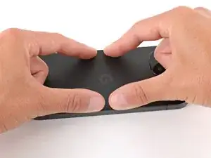
    • If the adhesive starts to pull up with the liner, lay it back in place and use your spudger to secure it again.

  75. TKV1xbIJJFskEGPl
    TKV1xbIJJFskEGPl
    eHHv2r2vMrKfS6cK
    • Use the pull tabs to remove the final liner from the rear cover adhesive.

  76. RnnmAFFeisYIr3F6
    RnnmAFFeisYIr3F6
    SK4Go2MpYpuuwYC6
    F34bmaOVHJIcy2Bi
    • Align the rear cover over the frame and press it into place.

  77. O1MWPAwCIuijhC5P
    O1MWPAwCIuijhC5P
    mnZHXKHGBWyqnac2
    VkGHwL6IGHpPjDD2
  78. JaLcj6UFZCskS4HG
    JaLcj6UFZCskS4HG
    xSHOvLNFNSuOUD3V
    2mAbJpmbaMsOrMRy
    • Push the SIM card tray completely into its slot on the bottom edge of your phone.

Conclusion

Congratulations on completing your repair!

Take your e-waste to an R2 or e-Stewards certified recycler.

To run a diagnostics test with the built-in Pixel Diagnostic tool, click here.

Repair didn’t go as planned? Try some basic troubleshooting, or ask our Answers community for help.

Spencer Day

Member since: 14/09/22

117606 Reputation

0 comments