Introduction

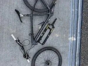
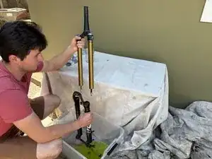
This guide will walk you through the steps of replacing seals on a Fox mountain bike fork (often called an "uppers service"). These steps can be applied to any modern Fox fork, though this guide focusses on a 2012 Fox 32 factory fork. Be sure to check the Fox website for the correct parts, fluid, and fluid volumes to use no matter what fork you are using (this will be done using the serial number on the fork).

  1. ZxGcxPZ5G4FN1HYi
    • Begin by finding a flat location to lay your bike down.

    • Be prepared for your bike to stay in this location until the fork has been serviced (potentially several hours).

  2. HQZpdCfLPSn4WaLi
    HQZpdCfLPSn4WaLi
    kEZ5QnVEiqCsTsnL
    vLeEgTUTDCFPo4mI
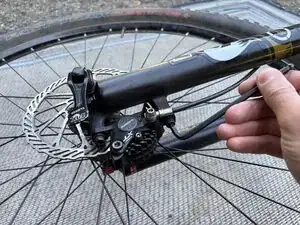
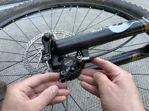
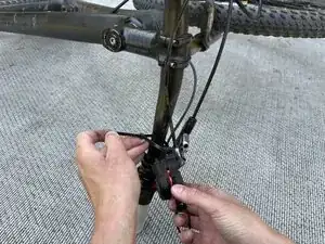
    • Begin to remove the front brake caliper. Find the appropriate sized Allen key from your set, and remove the bolt by turning it counter clockwise.

  3. WFtZLrSkg6nDeXkb
    WFtZLrSkg6nDeXkb
    LHnDRkEtCNJQvEvI
    sGF64ZbPw2teajZI
    • Remove the second front brake caliper bolt by unscrewing it counter clockwise.

  4. JCAilVlRPYeKwPh2
    JCAilVlRPYeKwPh2
    jgYbwQOgSFtgnIje
    • Remove the front brake caliper.

  5. GkGMXFDW5IZVBEIF
    GkGMXFDW5IZVBEIF
    uKcCPalVTQILMMkV
    2pAGj6KXvNHIhKxW
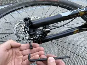
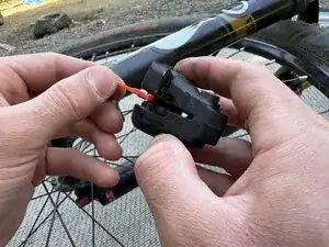
    • Insert the caliper pad spacer to ensure the pistons cannot move while the caliper is off the fork.

    • You can alternatively use a wooden shim to keep the brake pads separated.

  6. eRruOhUFLrXTJAMC
    eRruOhUFLrXTJAMC
    pWqJuZ4ZnXhJM1ML
    • Reinstall the brake caliper bolts into the fork for safe keeping. Insert and turn clockwise.

  7. yGTdshXGPQglpLF4
    yGTdshXGPQglpLF4
    Os2RGpnl5KxGKTTq
    g2J1iIHNMKqr1LGx
    • Use a zip tie to secure the brake caliper to the handle bars.

    • This step will ensure the brake caliper does not move around excessively and stress the brake line.

  8. h3CAeU3cbXZ4NhBP
    h3CAeU3cbXZ4NhBP
    TVXVrBX2nrEJM1hZ
    r6MqYFcMmnaTPEd6
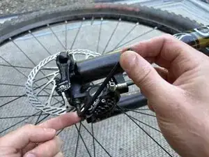
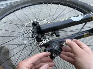
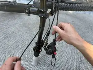
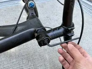
    • Find the correct Allen key to remove the brake line bracket from the fork.

    • Remove by turning the bolt counter clockwise.

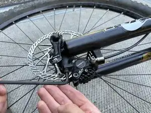
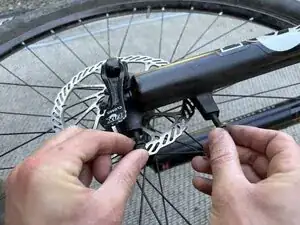
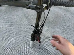
    • After the brake line is removed from the bracket, screw the bracket back onto the fork.

  9. BRSsLLp1g2DFDWPd
    BRSsLLp1g2DFDWPd
    A64DMc5YfEg1b3VB
    4aRPVYkH5MWUtS3b
    • Remove the thru-axle by flipping the lever down and unscrewing counter clockwise.

  10. ijmxmMuM1tPUKgf2
    ijmxmMuM1tPUKgf2
    JJMjuCRQCcFWZmAX
    WiWVYBFDVfG3MxXT
    • Remove the wheel from the fork.

    • Set aside for safe keeping.

  11. Z4eOmqZd5HI2yexG
    Z4eOmqZd5HI2yexG
    2lrfAAbGEHZHaSVq
    vZn2QstC1LbDQma2
    • Reinsert the thru-axle into the fork for safe keeping.

  12. wqATMKRgc2dsIYcZ
    wqATMKRgc2dsIYcZ
    DIyYn5KEIyfNREuK
    cGAMcDyb4nXikHEV
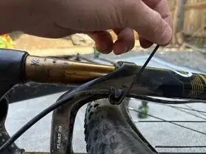
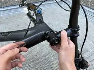
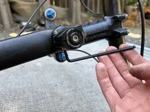
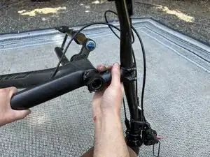
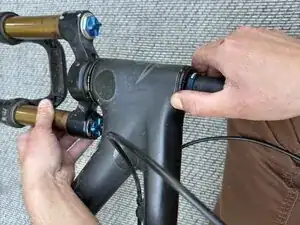
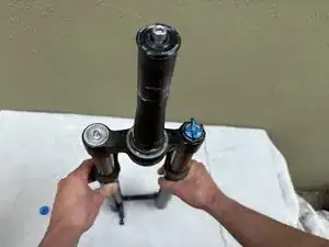
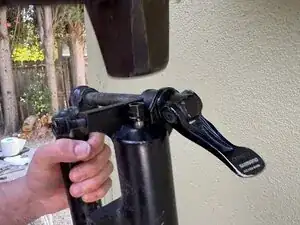
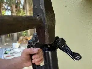
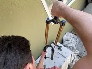
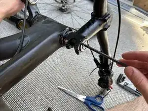
    • Find the proper sized Allen key to loosen the stem clamp bolts.

    • Loosen each stem bolt at least 3 turns by turning counter clock wise.

    • Do not remove the bolts entirely.

  13. rfxNd6GsFGWLLDiM
    rfxNd6GsFGWLLDiM
    aaJS5HLcrdoBLkaP
    GPXJAVGsKFsfAf5O
    • Loosen the second stem bolt by turning counter clockwise at least 3 turns

  14. 3ScsK6lDqGSKOIxN
    3ScsK6lDqGSKOIxN
    V2hatdXbAWbGWjLv
    i2N2EJWJccXPxE34
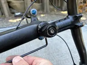
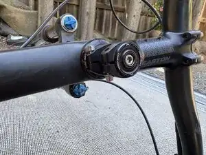
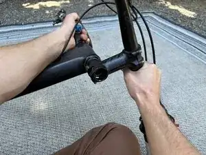
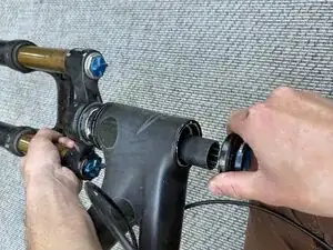
    • Find the appropriate sized Allen key to fit the stem bolt.

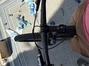
    • Remove the stem cap by turning the bolt counter clockwise.

  15. ZQOWpdPc5QjfGITb
    ZQOWpdPc5QjfGITb
    PsrYnJD1JxusHofY
    vNuSFZPPu6duuDdu
    • Slide the stem off the steer tube.

  16. qM4W2LqLKAZMsuRU
    qM4W2LqLKAZMsuRU
    oVYPQoKUFxWNA4Rq
    sOZQbhkZtNHT3EPX
    • Begin to slide the steer tube out of the frame.

  17. XZuHFDWTPIWNFsHU
    XZuHFDWTPIWNFsHU
    h6mxZgsvYGVrhkKL
    P1VTOmsuesVTi6Vf
    • Remove the upper portion of the headset.

  18. fngLiLD3wqMYKqNG
    fngLiLD3wqMYKqNG
    D1DOaPW3vJTLdfsH
    DojJEWA2LZOIUqcs
    • Zip tie the headset components to the frame for safe keeping.

  19. BV3Yf1ANyVRaIRVl
    • This is all the disassembly that should have been done. Keep everything organized for easy assembly!

  20. MuMmEGtrRqRuYucO
    MuMmEGtrRqRuYucO
    NFuRJG2MHZpvqMP2
    JaxLCA2FYGHw12uu
    • Screw the top cap back into the steer tube on the fork for safe keeping.

  21. J5ohXPQNRktOFhYX
    J5ohXPQNRktOFhYX
    QgDuXrmGsfoKOkdS
    ndSo4D3khBRyUq1t
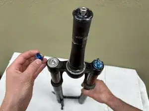
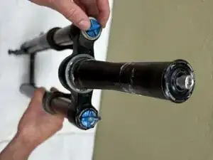
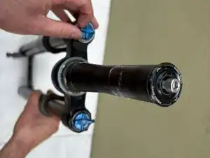
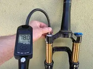
    • Remove the cap on the left side of the fork by turning counter clockwise, exposing an air valve.

  22. ZrWqq3viv6eqlalY
    ZrWqq3viv6eqlalY
    WD5sDj6vYHbofDcS
    1jTGpnBSSPPEwHSn
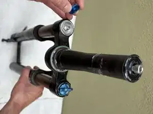
    • Use a small allen key (2.5mm was used in this case) to release all of the air from the fork.

    • Notice how the fork compresses when all the air has been released.

  23. xDIBnjuKlII4A1Wt
    xDIBnjuKlII4A1Wt
    SbbXJEMXeQlfCwaQ
    aVZmKoAIJUYAXFZw
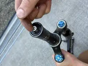
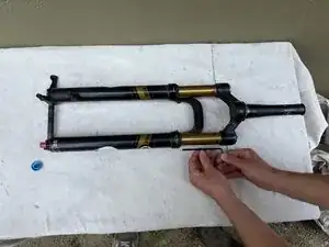
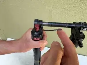
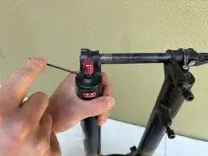
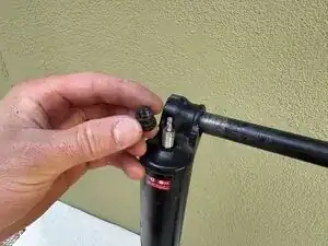
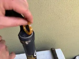
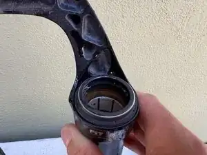
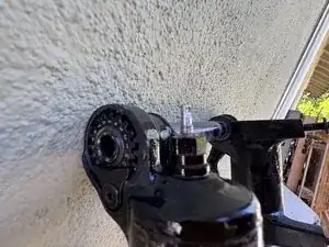
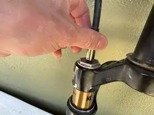
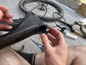
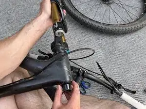
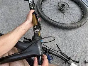
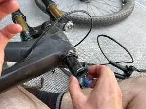
    • On a work surface, flip the fork upside down and locate the red rebound knob.

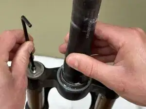
    • Locate the small allen bolt and find the appropriate sized allen key. Loosen the bolt by turning counter clockwise 3 rotations and remove the rebound knob.

  24. IoVxVDM1WGq1ScTY
    IoVxVDM1WGq1ScTY
    H2fnOKIQDIoX2YfH
    opRVSQGy3JaVaZQx
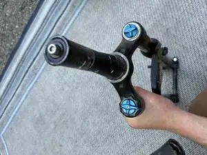
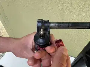
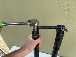
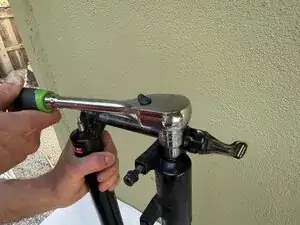
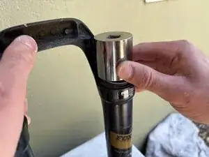
    • Find the appropriate sized hex socket to fit the nut that is under the rebound knob. Remove by turning counter clockwise.

    • Note: Keep in mind a long socket handle may make removal easier.

  25. eu3ryABevttkKSKL
    eu3ryABevttkKSKL
    Hids53dJPjNxaKrj
    LeZZVLR2bAPtieww
    • Remove the nut on the bottom of the other stanchion using the same process.

    • The nut size should be the same.

  26. CjMEWPkGFT42Wpp5
    CjMEWPkGFT42Wpp5
    uAAbxTDrF55BisyV
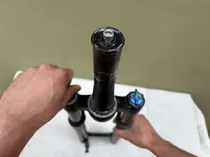
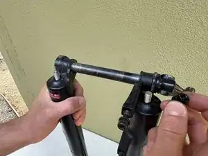
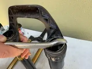
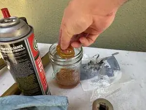
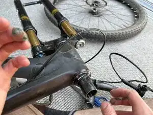
    • Find a small socket that will rest on the shoulder below the threads but not damage the threads on the rebound side of the fork.

    • Use a soft headed mallet to lightly tap on the socket.

  27. auADQgASaTcjcyNi
    auADQgASaTcjcyNi
    IpNIMlPkLecR6dSO
    BD1eTjXLRHMNXJQK
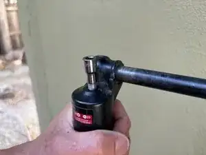
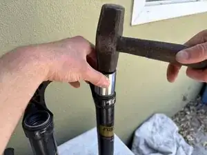
    • Screw the nut part way onto the threads on the other side.

    • Use a soft headed mallet and lightly tap on the nut.

    • Remove the nut and socket from the threaded parts of the fork.

    • Keep the fork inverted for the entirety of this step.

  28. 1EECNQUbmFNTsALp
    1EECNQUbmFNTsALp
    uNrwkbHVDC2c2KQH
    n6iWv2rpsVUmuUA6
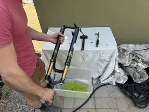
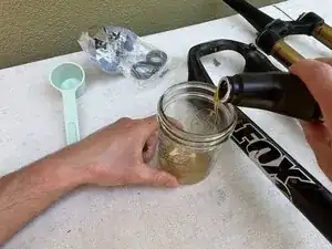
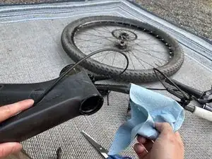
    • Get a large container to capture the oil inside the fork.

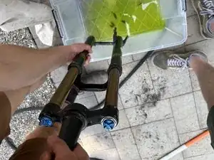
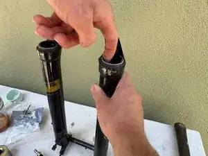
    • Flip the fork over above the large container, keeping in mind that oil will begin to flow out once the fork is turned right side up.

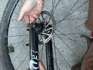
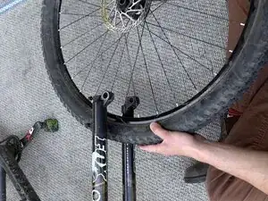
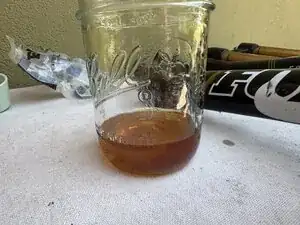
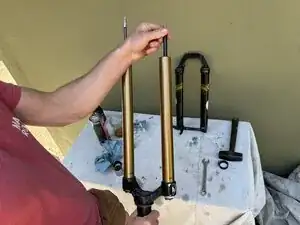
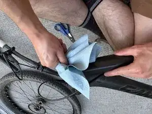
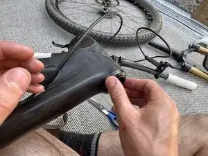
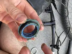
    • Hold the fork above this container and slide the stanchions out of the fork body.

  29. MHVRcnCSLaF2BwHA
    • The stanchions should now be separated from the fork.

  30. wqMcaI3DcRvn5Iba
    wqMcaI3DcRvn5Iba
    dMVWK4UISQqTEGHM
    p4GyeS5BGPDaceK3
    • Use a flat wrench to pry the dust seals out of the fork body.

    • Be very careful to not scratch the inside of the fork body with the wrench.

  31. HH4c2UDHFaeAvgNl
    • Perform this step on the other side of the fork body.

  32. g3RHUUYvaKIQSQEe
    g3RHUUYvaKIQSQEe
    eOJ1RTWFdYvV2kAj
    vAgYrEDrFjnRqTHQ
    • Use a rag to clean the surface that the dust seal sits on.

    • There is likely lots of dust on and around this surface, so wipe it down well.

  33. jbRkpSggTq5iH2IB
    jbRkpSggTq5iH2IB
    Y1tXKVmEOOTgjSUF
    XFQH5UfGAQKhxYTB
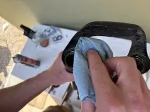
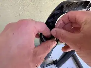
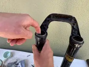
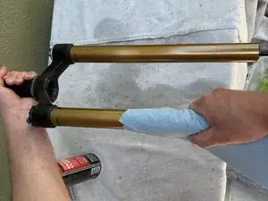
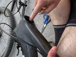
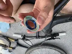
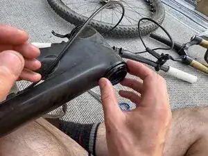
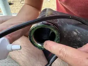
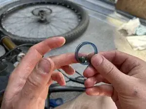
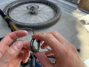
    • Rest the new dust seal over where the old one was removed.

    • The metal ring should be facing down.

    • Use a socket the same diameter of the dust seal and a mallet to seat the dust seals.

    • Be very gentle and do not damage the dust seals. It may take several small taps.

  34. m2UYtARBMqqmOCYH
    • Both dust seals should now be seated in the fork body.

  35. EQBwLlsCkPVNkOqj
    EQBwLlsCkPVNkOqj
    1yJlwpxAMONWOfqn
    krOhOyTJEue3tL5t
    • Soak the white bushings in fork oil.

    • Pour enough oil to cover the bushings

  36. 5DSM5TJRTpP1jMOT
    5DSM5TJRTpP1jMOT
    hkNv2dWZEKEsHORZ
    eXdCT1yD6GRipVKm
    • After letting the bushings soak for ~5 minutes, insert them into the dust wipers.

    • They should easily seat in place. The oil will help keep a seal and provide lubrication.

  37. dAuYkOjKISMbZRda
    dAuYkOjKISMbZRda
    5uBINf24abZ4ZTTL
    iMTgLooV6ZnPFHw5
    • This is now how the dust seals should look.

  38. vdMTTKwObXYUiPVF
    vdMTTKwObXYUiPVF
    22KoOEbyblNecVVN
    3xjZNYonLRUcJSMs
    • Apply a small drop of grease to the inside of each dust seal.

  39. SUUQR5CZavEUtsbZ
    SUUQR5CZavEUtsbZ
    1Fg3UURLOFuya4jL
    6CgCQEFbwMDqFqeN
    • Use brake clean or another degreaser to clean the stanchions.

  40. Ab1TbQJ1RTGpehDI
    Ab1TbQJ1RTGpehDI
    SmvsYBFrl4jc2HmS
    2Tg6WdpmDxX1okTj
    • Be sure the rods in the bottom of the stanchions are fully extended.

  41. oylRdhIDEpvfBEiP
    oylRdhIDEpvfBEiP
    uYlvl5uGuUIFlZoc
    • Insert the fork stanchions into the fork body part way.

    • Do not fully insert.

  42. M4Zktt1kPHjD3pq2
    M4Zktt1kPHjD3pq2
    owKOR5PDEpSKFAFx
    ULSQYuc3IZ4CEesh
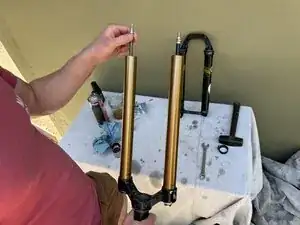
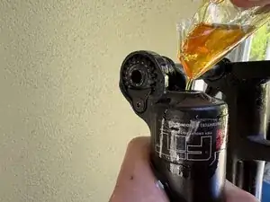
    • Using the serial number on your fork, determine from the manufacturer website how much oil should be added to each side of the fork.

    • In this case, it was 30 mL total.

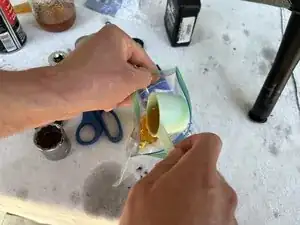
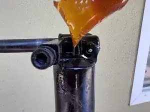
    • Dump the measured quantity of oil into a plastic bag. Close the bag, invert, and cut a small part of a corner off.

  43. MmsHFVSBhMMUdNyG
    MmsHFVSBhMMUdNyG
    cNiFSBYSVLjFTI6G
    d2dpAVhmFQTNRwSo
    • Pipe the fluid into the bottom of the fork body.

    • This fork used an equal amount of oil for each side. If the manufacturer recommends a different amount of oil for each side, it may be wise to measure and pipe oil into each side separately.

  44. tLjsv3wQCIfL2tYB
    tLjsv3wQCIfL2tYB
    jYjiAZJYUduXfNtX
    • Compress the fork enough for the threaded nipples to come through the bottom of the fork.

    • Keep the fork inverted for the remainder of the assembly.

  45. yKdELLW2dhTZkClu
    yKdELLW2dhTZkClu
    23t6EtMWLcYYUX3P
    tsnsHiWHZHF12xcO
    • Thread the nut onto each nipple by hand.

  46. SqaBCVOYnX2HdPRc
    SqaBCVOYnX2HdPRc
    4JpMFGSP5eIG351X
    yAeWtZ1KPAyGHnCV
    • Use a socket to tighten each nut.

    • They should be tight, but do not need to be cranked down.

  47. CRhrBM5XaOigjhDT
    CRhrBM5XaOigjhDT
    6N3IWKsvFda3KHcG
    PGLRF6cPWGDHURxp
    • Reinstall the rebound knob.

    • Turn the Allen bolt clockwise to secure the knob.

  48. smcDXbYLQMjrrgOQ
    smcDXbYLQMjrrgOQ
    B3SphFcqNmiXhYW2
    aRempKOyhNWPWAQE
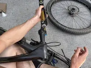
    • At this point, the fork can be turned right side up.

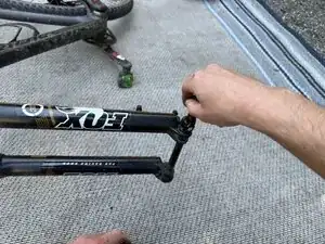
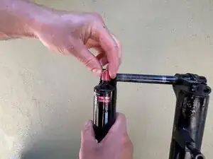
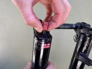
    • Unscrew the cap covering the air input (opposite side from the damper).

  49. mLrqUnfX6iGFDCYo
    mLrqUnfX6iGFDCYo
    mEXUlO2PLFRgwdfT
    tTk1SPEfjdKQM1LK
    • Use a shock pump to air the fork to the desired pressure.

    • As a rule of thumb, this should be about 50% of rider weight in PSI. Consult the manufacturer website or manual for a more precise value.

  50. nOgBELGhnQGPBfCT
    nOgBELGhnQGPBfCT
    RCEqYoJbWbrUfZvi
    MLDkQlqIbGoCxG2E
    • Clean the inside of the head tube using a clean rag.

    • Be sure to remove as much old grease as possible.

  51. ZgOSGPqBEsiBoEjq
    ZgOSGPqBEsiBoEjq
    VGZDQDBiggAiUCJ5
    rAFCIXBpIfstY2Gx
    • Apply a drop of grease to the inside of the head tube.

  52. mpoHPi3FtUnwlTpi
    mpoHPi3FtUnwlTpi
    JGuVmtwHRwZiGK4L
    • Regrease the head set component removed earlier.

  53. DUYKGitacl2KvsBh
    DUYKGitacl2KvsBh
    Yopq1KtWqvCPniAS
    xXAWTBXIVQDODl4i
    • Reinsert the headset component back into the frame.

  54. mlvoCZrUQcWSO1Ck
    mlvoCZrUQcWSO1Ck
    hJE1cvUnFpLUwRRm
    nspoHmSxCSNCSAF2
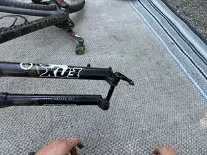
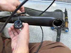
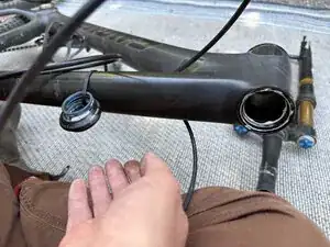
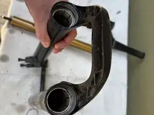
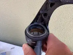
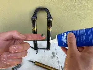
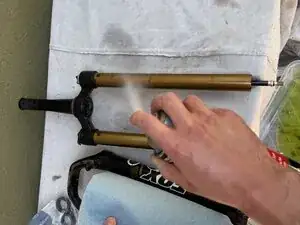
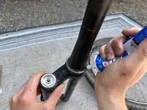
    • Grease the headset component in the bottom of the head tube, and the base of the steer tube.

  55. ZHjt53WnBpoEvreP
    ZHjt53WnBpoEvreP
    Ttpxh34yyCKBDsZF
    pMU5vZk2PIMVUmZ4
    • Insert the fork back into the frame.

    • Be careful when reinstalling so that no parts of the headset assembly are knocked off during reassembly.

  56. EFASWP1kHPABuLTb
    EFASWP1kHPABuLTb
    WObBsJNYGqAJUFRK
    • Grease the spacer that goes onto the steer tube.

  57. JXp2uaQX2DerAldR
    JXp2uaQX2DerAldR
    pfcWw6YFbdCdicjX
    gfPkqUrR6WovZ1yn
    • Reinsert the stem spacer onto the steer tube.

    • From here on, assembly is the reverse of disassembly.

  58. QVGkphAXMO6yQnwI
    QVGkphAXMO6yQnwI
    gLipZZMHFKJfFtOF
    l3gZB1YKLk3qyINq
    • When reinstalling the handlebars, ensure they are aligned with the front wheel. This is best done by standing over the bike and looking down on the handlebars and wheels.

Conclusion

To reassemble your device, follow these instructions in reverse order.

Aidan

Member since: 09/04/25

757 Reputation

0 comments