Introduction

Use the guide to learn how to replace the motherboard for the Bowers and Wilkins T7 Bluetooth Speaker.

  1. N2525s6dc3sJspP1
    • As with all electronic devices, make sure your device is powered off before you begin.

    • Gently lift up the access panel; it should easily "pop" open.

    My model does not have screws in the front as indicates here. Not sure what to do now

    thebolts -

  2. xThTyJJY5oHohmKt
    • Remove 14mm screws on the front panel with a J1 Phillips head screwdriver.

    • There are 8 screws in total.

    FYI: I bought the Ifixit toolkit and sadly the screw driver isn’t long enough to remove the 4 middle screws.

    Jonathan Keay -

    What sizes are the screws exactly? I took mine apart and someone threw out the screws so now I need replacements.

    Pablo Escobar -

  3. jFyPWLe1ZGONodiA
    jFyPWLe1ZGONodiA
    Q6GwhQKcdGPp14yt
    • Be gentle, the rubber seal is fragile and easy to tear, resulting in cosmetic damage to your device.

    • Using the ifixit Opening Tool, carefully pry off the rubber seal around the sides.

    • The seal is held by adhesive, if this is proving difficult you can use a heat gun to help the process.

  4. 22KDuTtIZaSCJ1rM
    22KDuTtIZaSCJ1rM
    rPAcdDNtXEhrTSjZ
    • The cover is the most difficult part to remove. As you work, pry continuously, moving the tool around the device, working it a little further as you go.

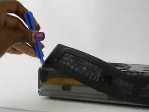
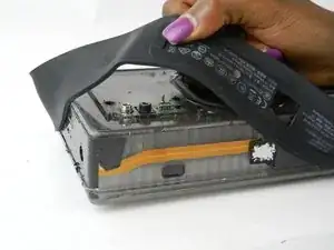
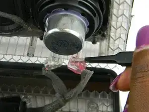
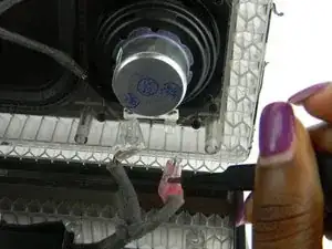
    • Using the ifixit Opening Tool, pry open at the seam found under the rubber seal.

    • As the cover starts to come off, you can lift up using your hand.

    I tried this with the ifixit tool, but I could not remove the cover

    m6rtg -

    I used a sharp knife. Note carefully where the seam is in the above diagram: on the back about 7 mm from the edge.

    al.germain -

    Remove the outer rubber completely. Then you need to peel back (or peel off) the black sticky tape from the sides nearest the front to reveal the seam. When all peeled back, the two halves come apart easily with no tools

    Matt -

  5. OiO5Y41xrxK6yWQ1
    OiO5Y41xrxK6yWQ1
    uHRErdgUTRbMmrpE
    U4VsyIDpwJTxYbCg
    • Gently squeeze the internal locking mechanism inside the red and white terminals with either your fingers or a pair of precision tweezers.

    • While squeezing the internal locking mechanism, pull back the terminal.

    • Repeat this process for the second speaker.

    You don't need to do this step for either speaker to replace the battery, the cables are long enough. The other end is easier to unplug anyway (red and white clips in the bottom left of the body, see picture from step 6)

    Matt -

  6. fOoOFoBcdnKXP1Si
    fOoOFoBcdnKXP1Si
    FkACdwGvOT2lJFDE
    hva1tiOMgO4DvqL4
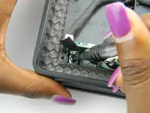
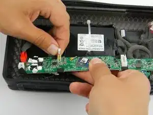
    • Remove the leftmost 14mm screw with the J1 screwdriver tip.

    • Remove the rightmost 14mm screw with the J1 screwdriver tip.

    • With the screws removed, the motherboard is now loose.

  7. od4ExoNGSIDVCLSQ
    od4ExoNGSIDVCLSQ
    3K6WlNyeVbDbTrGK
    MRTDHKjDniRvpowx
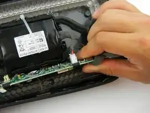
    • Ensure you position your fingers, or a screwdriver tool with the 0.8 tip, in a position on the outside of the black tab.

    • It is advisable to use a nylon spudger to accomplish this task, because using a metal screwdriver like the one used in the image, can be unnecessarily dangerous around delicate connectors and the motherboard in general.

    • When working with electronics, it's important to choose a tool that's ESD-safe to avoid accidental damage.

    • Slide the black tab out so the cable is able to be removed.

    • At this point, the cable is removed.

    • These ports are difficult, as you need to simultaneously push the black tab while pulling the cable.

  8. alaiMqkJitACE2Ub
    • Pull out the cable that is attached to a port under the motherboard.

  9. IGUZpMOXX6FSTGcN
    IGUZpMOXX6FSTGcN
    HPkKusIkasOmbkwV
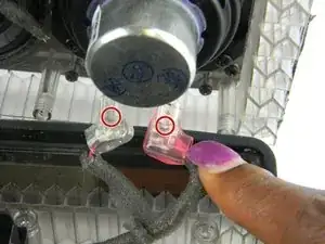
    • Use the 0.8 and 1.0 screwdriver tips to press on the pins to release this cable.

    • The cable should slide out when the releases are pressed.

    • This cable can be difficult, as you need to simultaneously push the pins as you pull out the cable.

  10. vM1EaMuMdbJ11OZe
    vM1EaMuMdbJ11OZe
    CDl3pgqZh2r2ZnjW
    • Use the 0.8 screwdriver tip to press in the tabs keeping this cable in place.

    • The cable should easily slide out.

  11. M1wxrQeWtCJUwDFu
    M1wxrQeWtCJUwDFu
    jabf5qgGMQPHRcbb
    • Rotated the motherboard to access this cable.

    • Use your fingers to pull out the cable.

  12. gmEjvO1BOEUtNCVQ
    gmEjvO1BOEUtNCVQ
    n1dMqJeUQrGHZTZE
    • The battery cable needs to be removed.

    • Use your fingers to pull the cable out of the port.

  13. UlYLrxk3POrDoSnE
    UlYLrxk3POrDoSnE
    rQcqBUMwxec5wQGs
    • The red cable has a tab to press in order to release the cable.

    • Slide out the cable while continuing to press and hold the tab.

  14. KrKtvRNaH56LYObH
    KrKtvRNaH56LYObH
    Xh2gpCqXJN4BbBuk
    • Rotate the motherboard to access the last cable.

    • Pull on the gold connector to disconnect the cable.

Conclusion

To reassemble your device, follow these instructions in reverse order.

Adam Kosianowski

Member since: 09/03/17

101 Reputation

One comment

OK, so now the motherboard is out. What can that acomplish? Where can you get a replacement? and where is there a circuit diagram to fault find??

james scanlon -