Introduction

This guide will instruct you on how to replace the hinges on your Acer Chromebook Spin 714 CP714-2W-56B2. This process can be difficult and time-consuming but with this guide it will make the process easier.

  1. ANV5MmEIfwxWKuFX
    ANV5MmEIfwxWKuFX
    gmtKBAF16KCiIibL
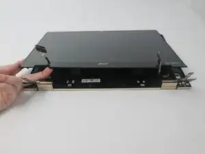
    • Flip the laptop to show the bottom side.

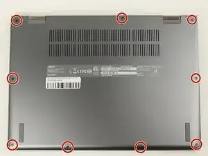
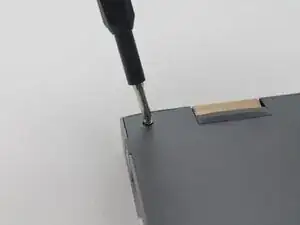
    • Remove the nine 6.5 mm screws using a JIS #1 screwdriver.

  2. Wkn1YlgNTRxc2BCJ
    Wkn1YlgNTRxc2BCJ
    UOcVUvnFJZaM2KUb
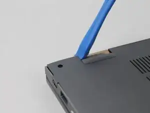
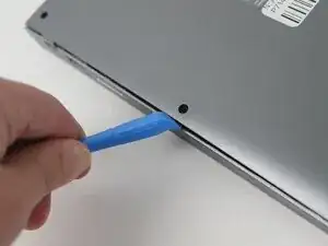
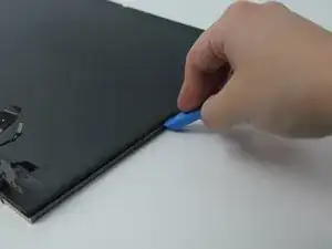
    • Use a plastic opening tool to separate the outer casing and panel; gently work the tool around the entire outer edge

    • The easiest place to start is at one of the hinges. The corners can be somewhat difficult.

    • Be gentle. The internal clips can snap.

  3. FKyUYKmuVpcePLkL
    • Peel off the tape covering the wires.

  4. SAEuY2TADcPy5e1b
    SAEuY2TADcPy5e1b
    chJNmJBN5DHYrsrm
    VfDJW4M6uoH3w1ka
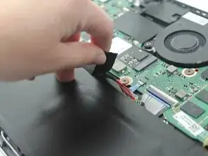
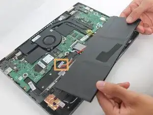
    • Lift the battery from its studs, and place it closer to you.

    • The battery is not clamped or screwed onto the frame. Once you disconnect the battery, you are able to safely remove it by picking it up.

    • Unplug the rainbow wires connecting the battery to the motherboard.

    • Be sure to only grab the white portion of the plug, do not overstretch the rainbow wires.

    • Remove the battery from the laptop.

  5. dMX14dR6yqjIUNXn
    dMX14dR6yqjIUNXn
    2kMpXZjSvd2G2nXc
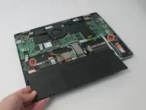
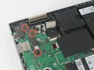
    • Remove the three 4.6 mm screws holding the left-side screen bracket to the internal components using a JIS #1 screwdriver.

  6. V6AgLmLTCKIsOeUJ
    • Flip the bracket away from its original location.

  7. mEElKbVaQPFXPxgh
    mEElKbVaQPFXPxgh
    hRNkYpBe6jbP26pY
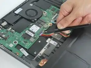
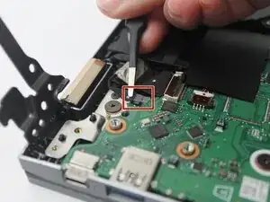
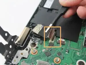
    • Remove the clear tape securing the smaller wire.

    • Flip the small black clip securing the larger wire.

    • The wire below loosely sits inside the plug. It is fine if it comes out on its own after the clip is opened.

  8. 5DTAHirp1FBxXQA5
    5DTAHirp1FBxXQA5
    CDlVhcjcLenQCBnq
    VqxjrE1xfuVVNCbO
    • Unplug the smaller wire.

    • Lift the larger wire, if it is still in place.

  9. giE5H1uHUrNlrWO3
    giE5H1uHUrNlrWO3
    fKXsMxXfKArUeLtv
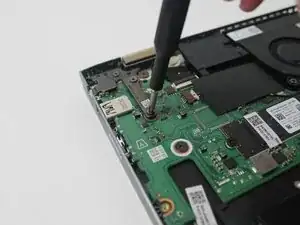
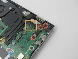
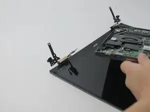
    • Remove the three 4.6 mm screws holding the right-side screen bracket to the internal components using a JIS #1 screwdriver.

    • Disconnect the ribbon cable from the motherboard.

    • There is only one wire on the right side. It's similar to the larger wire on the previous side, but slightly wider.

  10. fZjSKmvsnjItolNN
    fZjSKmvsnjItolNN
    NBD4BWCKdjhCwdjs
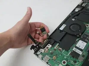
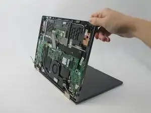
    • Remove the panel you've been working on.

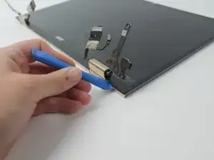
    • Lift from the front edge of the panel, so that it and the screen form a 90 degree angle.

    • Pull the electrical panel straight back, away from the hinges/brackets. It shouldn't require any force.

  11. rJAUBJjelTEfy4pL
    rJAUBJjelTEfy4pL
    OvQWixknsRCCsctD
    • Separate the screen from the top casing using an opening tool.

  12. VNWFkq6DfdMAmSIT
    VNWFkq6DfdMAmSIT
    cR3HGTmiXrHWJW4c
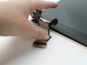
    • Untuck the wires next to hinges.

    • Lift the corner of the screen respective to the first hinge. Maneuver the wire around the edge of the screen on the other side of the hinge. Gently press the wire down onto your work surface.

  13. WEJvRxjsO6JgmSOW
    • Lift the screen from the hinge casing.

Conclusion

To reassemble your device, follow these instructions in reverse order.

Ariana Lafitte

Member since: 19/02/25

469 Reputation

0 comments