Introduction
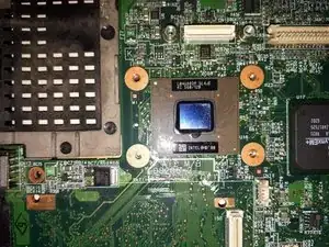
This guide shows how to disassemble the IBM ThinkPad i Series 1200. In addition, it explains how to remove the microprocessor to change its thermal paste.
Tools
-
-
Before beginning, ensure the notebook is powered off.
-
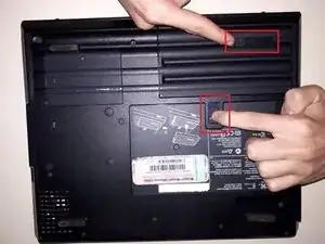
To remove it, slide the two switches in such a way that it is unlocked, as shown in the picture, and then remove it.
-
-
-
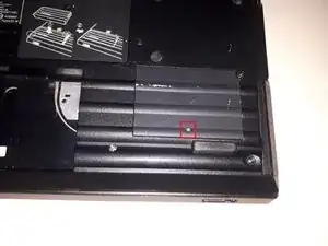
Remove the screw in the lower corner.
-
Remove the "cover" of the disk.
-
Pull the "hook" that is attached to the disc to remove it.
-
-
-
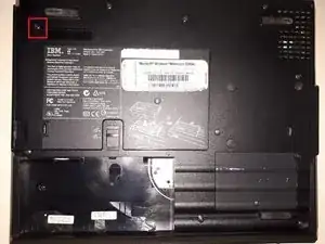
Remove the indicated screw from the backside of the notebook.
-
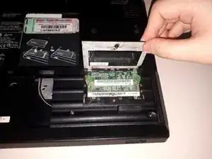
Take off the cover that protects the RAM memory.
-
-
-
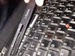
Slide the keyboard down so that the covers from above aren't blocked and as so we will be able to remove them more easily.
-
Disconnect the two ribbon cables that are located on the underside of the keyboard.
-
-
-
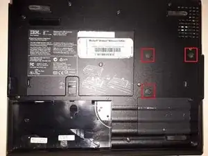
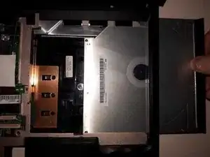
Remove the indicated screws from the backside of the PC.
-
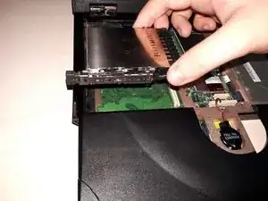
Remove the optical drive by simply sliding it out.
-
-
-
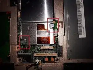
First, remove the plastic components indicated.
-
Remove the two screws that are found after step one.
-
Remove the plastic protector that is found on the upper part.
-
-
-
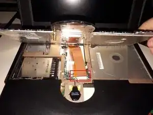
Remove the two indicated screws.
-
Proceed by removing the two connectors that are found there.
-
-
-
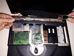
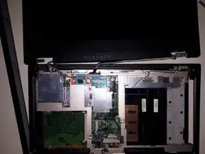
Remove the plastic frame that surround the netbook.
-
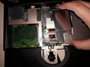
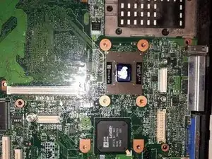
Remove the metallic protector.
-
Put aside the CPU cooler.
-
-
-
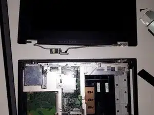
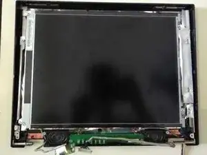
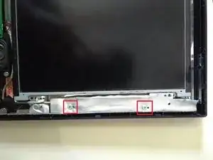
Remove the indicated screws that hold the metallic covering.
-
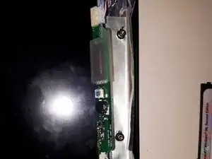
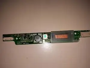
Underneath you will find the inverter.
-
-
-
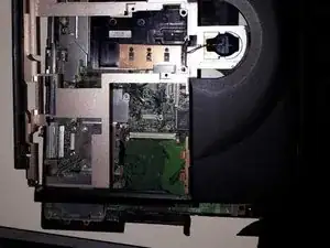
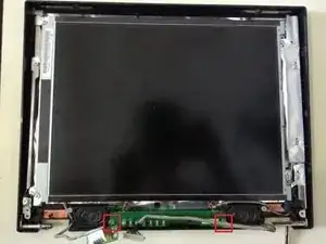
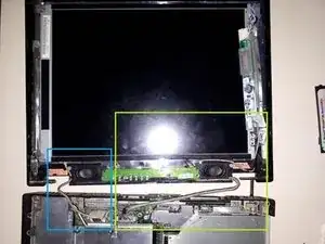
Power supply connectors from motherboard to inverter.
-
Data cables from motherboard to display.
-


To reassemble your device, follow these instructions in reverse order.
