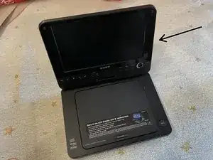
Introduction
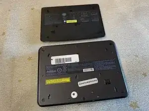
This guide goes over disassembling both the bottom and top halves of the DVD player. To reassemble, follow the steps of this guide in reverse.
It is possible to only disassemble the top half, though it is a little more of a hassle because of the bottom of the device. If you wish to only take apart the top half, skip to Step 19.
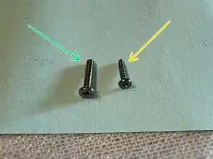
There are pictures of the screws attached as well. If there aren't photos, assume the previous photo is still relevant.
Tools
-
-
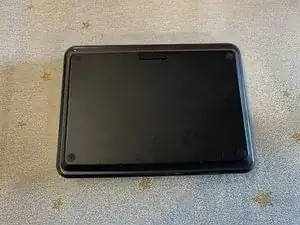
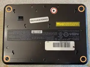
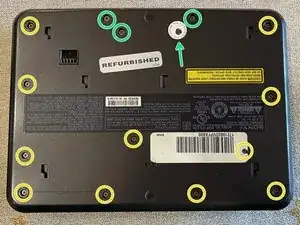
There are 10 visible screws on the bottom, 11 if your warranty sticker is broken.
-
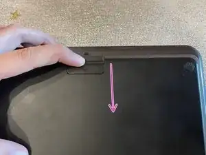
The footpads in the corners cover 4 more screws, so we must remove them.
-
-
-
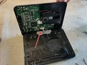
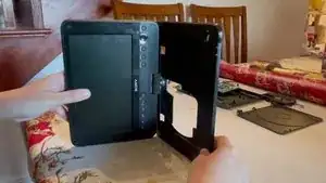
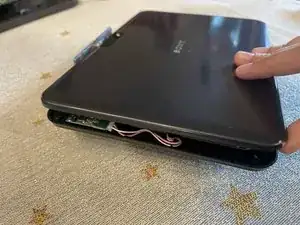
Rotate your unit 90 degrees and lift the cover up slightly, then tilt it towards the hinge (backwards).
-
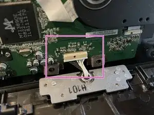
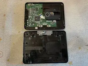
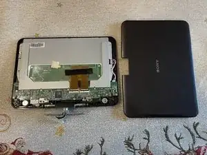
Remove the connector of the cable from the motherboard. The bottom half can then be completely separated.
-
-
-
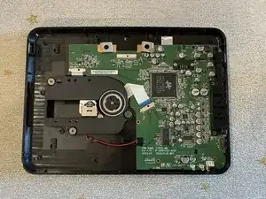
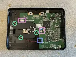
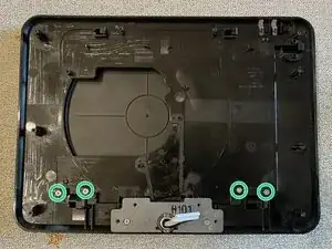
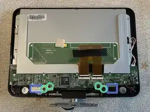
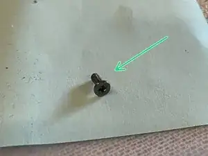
Three large screws hold down the laser to the cover, so we must remove them before working with the motherboard.
-
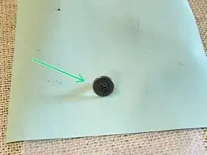
3 x 2.5mm
-
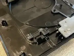
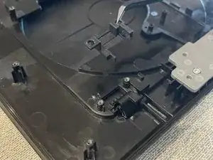
The laser is still attached to the motherboard by a few cables.
-
2 x ribbon cables
-
1 x connector
-
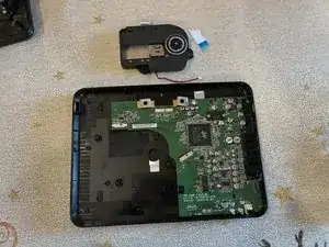
The laser can now be lifted off of the shell.
-
-
-
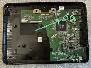
Remove the screws near the battery connector that hold the motherboard to the shell.
-
2 x 2.5mm
-
Take the motherboard out of the shell by pulling it outwards, so that the plastic connector sockets on the board slide out of the housing.
-
-
-
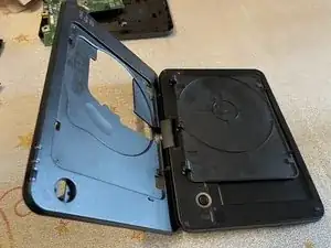
We can remove the open button mechanism from the disc tray.
-
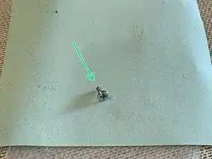
Remove the spring that holds the open button in the closed position.
-
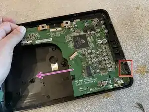
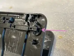
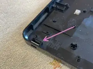
Pop out the open button by pushing the plastic on the edge in and downwards.
-
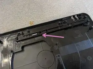
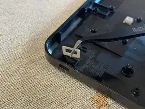
Push the long plastic away from the open button hole, then lift it out of the cover.
-
-
-
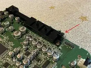
If you wish to get a better look at the socket connectors, we can remove another piece of plastic off of the motherboard.
-
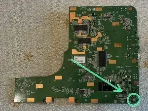
Flip the motherboard over and remove the screw in the corner.
-
1 x 2.5mm
-
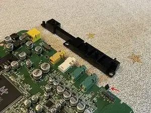
Bend the component on the side that keeps the plastic in place.
-
Lift off the black plastic on top of the connectors.
-
-
-
There are 4 screws keeping the DVD cover hinges in place that need to be removed.
-
4 x 2.5mm
-
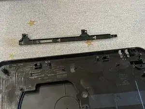
After removing the screws, the 2 black plastic pieces there can be popped off.
-
-
-
Open up the unit to about 90 degrees and open the DVD tray.
-
From the inside of the tray, pop out another black piece of plastic in the center of the tray.
-
-
-
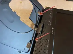
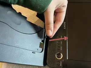
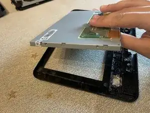
Open the unit to more than 90 degrees, and turn it so that the screen is on the right.
-
Gently push the DVD cover away from you. It should pop out and now can be removed.
-
-
-
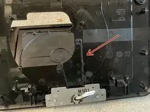
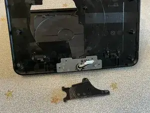
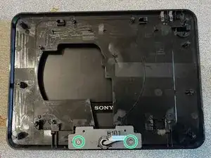
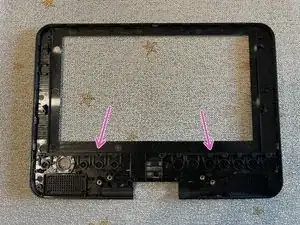
Back on the inside, we have to remove two more screws before the top half can be freed.
-
2 x 2.5mm
-
-
-
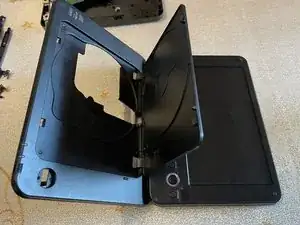
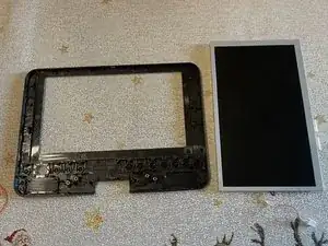
Open up the unit again.
-
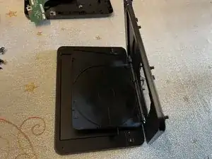
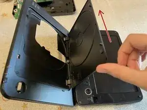
Now that the bottom and top are no longer attached, we can rotate the top out of the bottom half.
-
Fit the hinge into the larger hole in the disc tray, and then pull the top out of the bottom half.
-
-
-
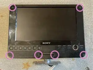
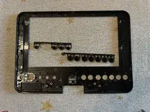
There are 6 screws holding the top half in place, all of which are under various pieces of silicone.
-
6 x 2.0mm
-
-
-
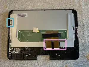
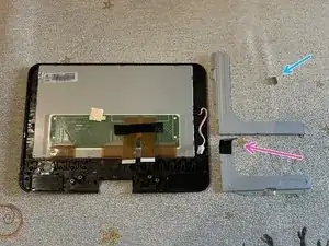
There are 4 screws holding the metal hinge in place.
-
4 x 2.5mm
-
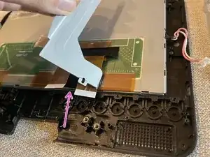
The hinge also has two connectors that must be removed.
-
2 x connector
-
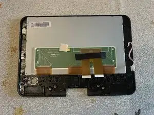
The hinge should lift right off.
-
-
-
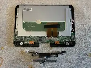
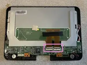
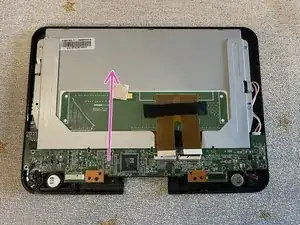
It is best to remove the cables connecting the screen to the motherboard before unscrewing it.
-
2 x ribbon cable
-
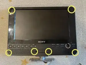
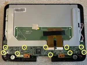
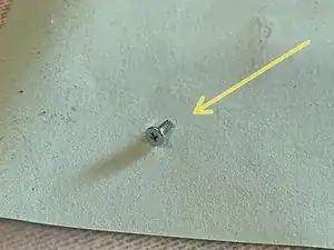
There are 10 screws holding the motherboard in place.
-
10 x 2.0mm
-
-
-
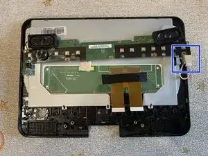
Flip the motherboard and speakers over to reveal the last connector.
-
1 x connector
-
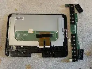
The motherboard and speakers are free to be removed.
-
-
-
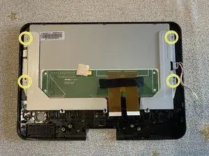
There are 4 more screws that hold down some metal parts securing the screen in place.
-
4 x 2.0mm
-
-
-
The left metal piece has a strong magnet that can be taken off. Take care not to lose it.
-
The right metal piece is taped onto the screen.
-