Introduction
Here's a step-by-step tutorial to dismount each piece of the NAS until you reach the motherboard.
'Note: the interest of this tutorial is however limited.'
Indeed, most of the components that a user can be brought to add or change are now accessible directly, without disassembly (storage disks, memory expansion).
*This is a step forward, the previous revision must be completely removed to change a single RAM array.
Only the memory stack on the motherboard and fans remain inaccessible directly and require the disassembly of the NAS described in this tutorial to be changed (whether they are HS or replace them by better components).
The dismantling time is estimated at one hour (but with photographies). That said, it is certainly achievable in 20/30 minutes.
The photographs were taken with an iPhone SE, using a portable LED studio.
- : info. must be checked.
-
-
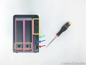
FRONT PANEL : you can notice on the right side, disks LEDs disapeared. You can find them now just on the top of the disk bays.
-
status LEDs
-
power buton (startup / shutdown)
-
1 x USB 3 port
-
"copy" buton
-
2 x disk support (caddy / cage)
-
disk bay lock
-
-
-
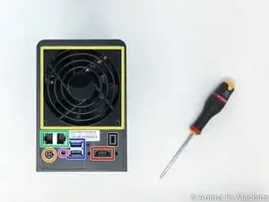
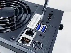
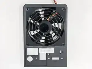
REAR PANEL
-
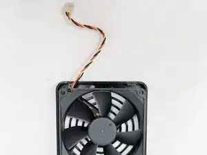
1 x 92mm fan
-
2 x EHTERNET RJ45 Gigabit port
-
2 x USB 3 port
-
1 x eSATA port
-
1 x power connector
-
1 x Kensington security incision (K-lock)
-
RESET buton
-
-
-
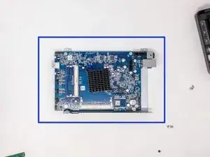
It's a new appreciable feature, the memory slots are now directly reachable.
-
first memory slot
-
seonc memory slot (not populated)
-
-
-
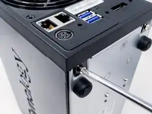
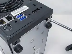
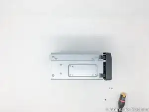
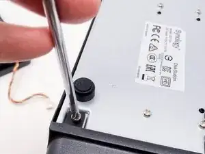
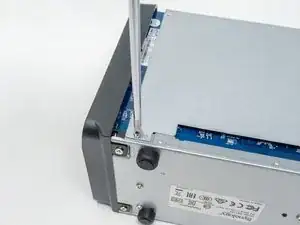
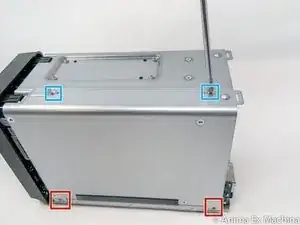
1 - Remove the two screws placed under the NAS, on rear side.
-
2 - Remove the screw placed in the middle of the rear panel.
-
-
-
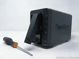
To remove the rear panel …
-
slightly pull the lower part of the rear panel so that the lugs do not touch the case, then ...
-
drag the facade upwards …
-
-
-
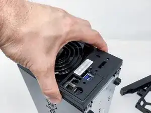
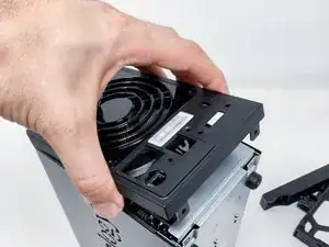
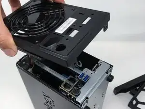
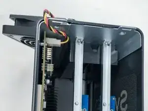
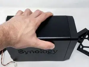
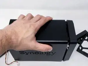
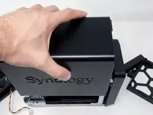
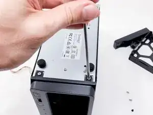
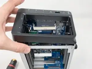
Once the rear panel is removed, the housing can be removed. To do so drag the cover about 1 cm to the back of the NAS then lift the hood upwards.
-
-
-
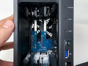
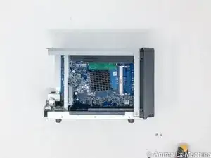
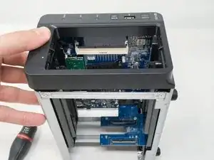
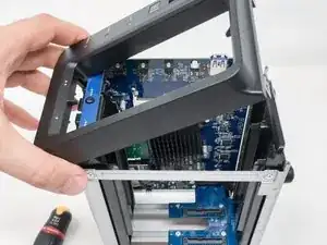
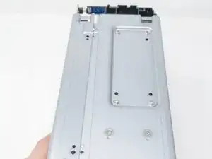
Now remains the front to remove ...
-
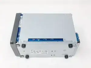
Here are some photographs of the case and the internal structure + screws.
-
-
-
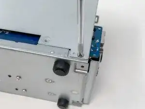
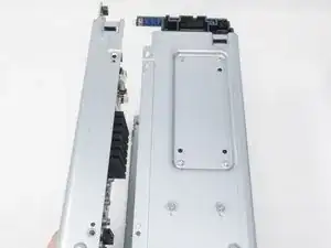
Remove the two screws under the box on the front side and then ...
-
in the same way as for the rear panel, lift the hood slightly ...
-
-
-
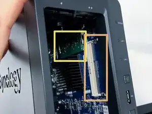
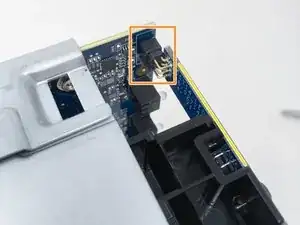
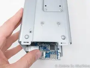
The guidance remains relatively accurate but the connector for the LED card drives is fragile. Do not force when removing or inserting the side flange.
-
electronic card LED disks
-
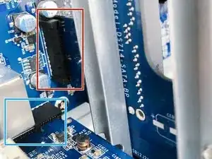
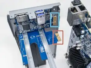
riser for SATA backplane (electronic card or daughter card)
-
electronic card riser (USB and e-SATA)
-
To reassemble your device, follow the instructions in reverse order.

4 comments
1 hour? I did it in 20 minutes that's teardown and reassembly!!?!
PLZ read the introduction more carefully !
How to replace a larger heat pipe radiator??
love3kkk -
Any suggestions on Mother board update for the DS218+ & DS718+ ?