Introduction
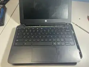
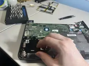
(Careful) Teardown of the HP model 11 of G5 EE, Commonly used in schools.
Graciously donated for guide making by my employer (IT department at school)
-
-
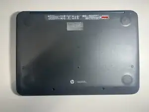
This is the HP Chromebook 11 G5 Education Edition, Commonly used in schools.
-
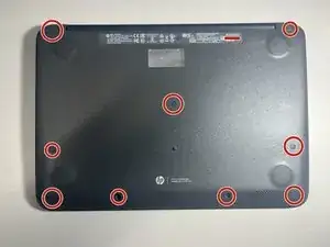
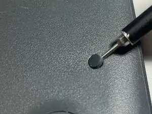
To start, remove all screws on the bottom of the device. This includes 10 PH1 screws, all of which are hidden by a rubber insert. This can be easily done with your smallest flat head screwdriver or something like a paperclip.
-
-
-
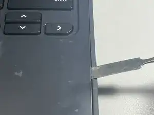
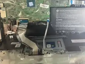
Flip the device over (and turn it off if it turns on) and remove the keyboard.
-
This can be done by prying the keyboard out working your way around the edges
-
-
-
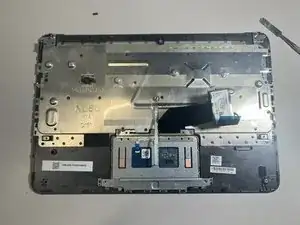
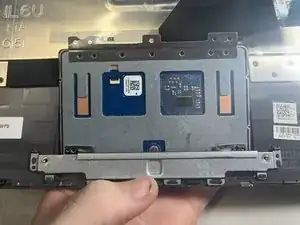
Turning our attention to the underside of the removed keyboard, the touchpad and it's ZIF cable can be seen.
-
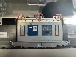
The touchpad can be pulled out by removing the 3 PH00 screws and popping it out by applying pressure to the other side, slightly towards the keyboard.
-
-
-
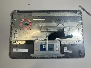
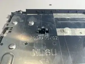
There is also a strange plastic piece that is removable. Given I have never had to deal with this in the entirety of working in school IT, I cannot assertively say what it is for.
-
Nonetheless, this piece can be removed by removing the single PH0 screw that fastens it in.
-
-
-
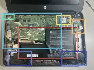
Turning our attention once again back to the main assembly, several core components can be immediately identified.
-
The Battery
-
The right USB daughterboard
-
WLAN/Bluetooth Card
-
DC Input barrel plug
-
The motherboard
-
The stereo speakers
-
-
-
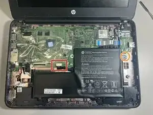
Starting with the removal of the battery, which appears to be made of 3 cells.
-
Disconnect the battery by pulling the cable out of the motherboard
-
The battery is held in with a single PH0 screw. Once removed, it can be pulled out.
-
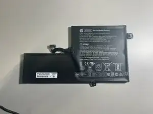
Opening up the battery does, indeed, affirm it is made of 3 cells, as wekk as a controller.
-
The battery appears to have an internal sensor for temperature, to protect against it exploding in unsafe environments.
-
-
-
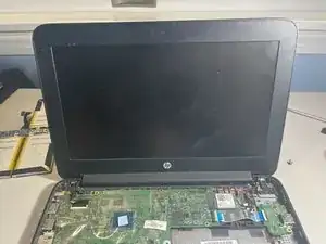
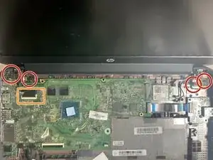
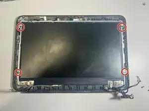
As for the display, it can be removed by unfastening 4 PH1 screws, 2 on each hinge.
-
Ensure you detach the display ZIF cable
-
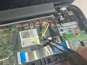
As well as the antenna cables on the WLAN card. you can do this by peeling back the protective plastic layer slightly to expose the connectors.
-
-
-
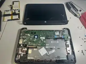
Once you have unscrewed and disconnected the display it can be removed by closing the lid, at which point it will "unhook" from the main body.
-
The display bezel can now be removed by prying along the edges.
-
-
-
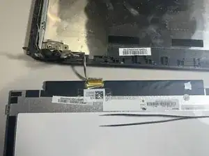
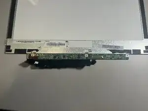
Now with the display assembly exposed, you the webcam (top board) and LCD itself can be seen.
-
The LCD can be detached by removing 4 PH1 screws, one in each corner.
-
This cable can be disconnected by peeling off the clear tape and pulling the cable out.
-
-
-
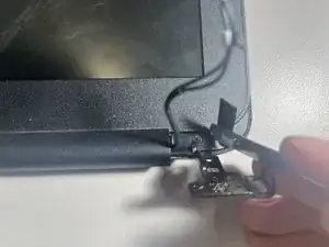
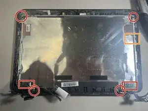
Focusing our attention back on the main body of the display you can remove the metal hinges from the top cover by removing 8 PH1 screws
-
There is also a sort of sticker holding the right hinge in. this can be carefully peeled off.
-
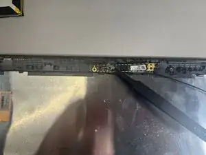
The display/webcam cable can be eased out by lightly pulling it out of its grooves, and disconnecting it from the webcam.
-
you can now remove the webcam by lightly prying it from the top cover, making sure to not actually break it.
-
-
-
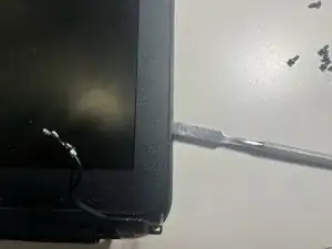
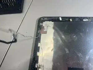
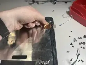
The antenna cables can be removed similarly to the display cables, except make sure to carefully peel the copper ends off, avoiding damage
-
-
-
We will now remove the WLAN card, this can be done by peeling back the protective plastic and removing the single PH1 screw and pulling out.
-
-
-
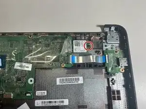
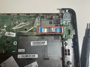
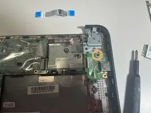
We can now remove the daughterboard by first removing the ZIF connecting it to the motherboard
-
Then, remove the single PH1 screw to release the board.
-
-
-
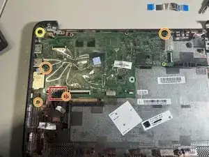
The motherboard is the next component to be removed.
-
First, disconnect the barrel plug from the motherboard.
-
Next, remove the 4 PH1 screws that secure the motherboard to the enclosure
-
Finally, remove the single PH1 screw securing the barrel plug to the enclosure, and remove the motherboard.
-
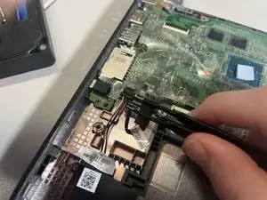
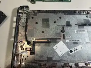
The barrel plug cable can then be pulled out with the barrel plug by simply lifting it off the enclosure, as it uses very little adhesive
-
