Introduction
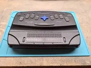
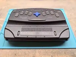
The Freedom Scientific PACmate is a series of Windows CE powered handheld PCs for the blind introduced in the 2000s. Our model is an original (non-Omni) BX400 unit running CE 4.1. BX indicates a Perkins style Braille Keyboard, and 400 indicates it was sold with a 20 cell swappable Braille display. We'll be exploring both in this guide.
-
-
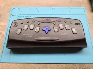
The unit has a Perkins style braille keyboard on the main body, along with the speaker, microphone, and cursor keys. A modular braille display is slotted into the bottom.
-
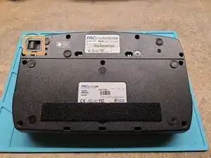
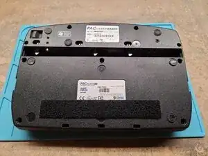
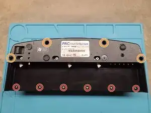
Flipping the unit over reveals the regulatory markings, along with the release for the braille display.
-
Pulling this lets us release the display to swap it, lighten up the unit and run without it, or even plug it into another computer. Neat!
-
-
-
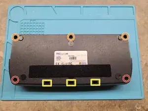
Let's start on the Braille display first. The Bottom cover is held on by 3 M3x7 screws on the back edge, and two more M3 screws on the front (missing from our unit)
-
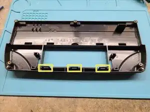
Finish releasing the top cover by insert a flat head screwdriver into the rectangular holes along the front and releasing the clips.
-
When the top cover is removed the scroll wheels will be free to move about. Note the orientation for reinstallation.
-
-
-
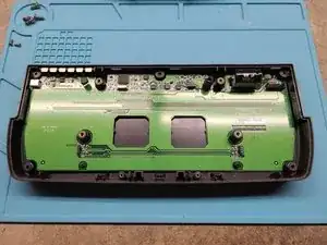
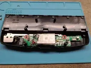
Now that we're inside, we have access to the braille display module.
-
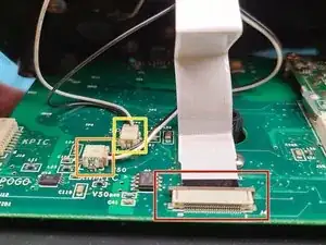
The module is held in with 4 M4 screws and 2 M2 screws. Once these are undone, unplug the connector in the upper right and lift the module out.
-
-
-
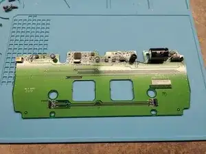
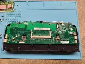
The display module holds the board in, so at this point we can just lift the board out. Let's take a closer look.
-
-
-
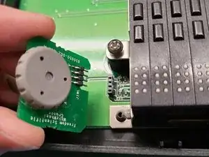
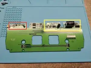
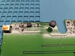
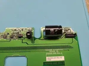
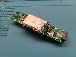
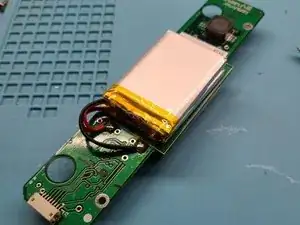
Looking at the board we see some odd things. It appears that an inductor has been replaced and a trace has been cut and bodge-wired around.
-
We wonder if this is a factory revision or later rework. It could explain the missing screws?
-
Either way we're tacking that inductor down with some glue so it stops rattling.
-
-
-
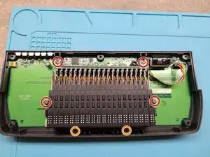
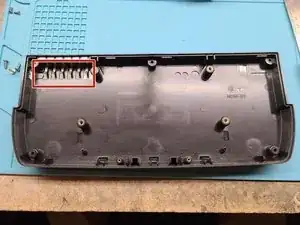
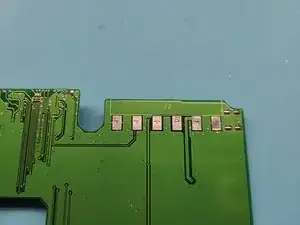
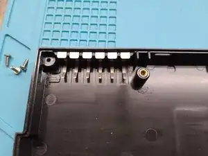
The board connects to the main unit through springy contacts embedded in the lower display base.
-
If these spring contacts or the spot on the board they rest against are corroded as on this unit, the braille display may not function correctly.
-
Cleaning these with emery cloth, steel wool, or a pencil eraser will get them shiny again.
-
-
-
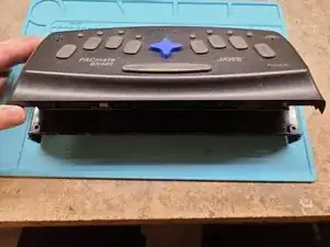
With the display module explored let's turn our attention back to the main unit. Looks kinda cute all by itself, doesn't it?
-
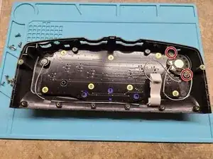
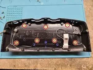
Flipping the unit over reveals 4 recessed M3x7 screws and 6 M3x4 screws holding the case together.
-
We can now pull the front edge of the unit up and towards us to release the catches, but be mindful as cables are still attached between the keyboard and motherboard.
-
-
-
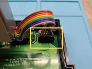
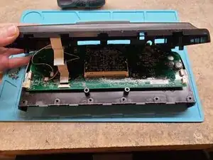
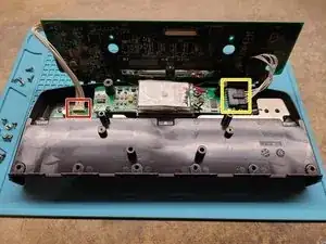
Lifting up the keyboard reveals the cables we need to disconnect. Two 2-pin connectors for the microphone and speaker, and another ribbon cable for the keyboard.
-
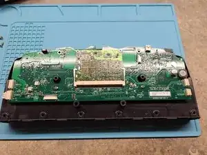
With the cabling free, we can lift off the keyboard and reveal the bare motherboard. Wait, is that a SODIMM module?
-
-
-
That is a SODIMM System on Module! Freedom Scientific seems to have used a modular architecture so the core system could be upgraded at a later date. From what I can tell, they later did so with the Omni series that has 128MB of ram.
-
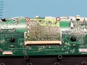
Two screws secure the System on Module, and then we can remove it by releasing the latches to the sides.
-
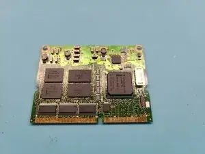
Pulling off the thermal pads gives us a better look at the 400MHz Intel XScale processor, 64MB RAM, and system Flash.
-
Could swapping this module let you DIY the Omni upgrade? We'd need to do more testing, but it's a strong possibility.
-
-
-
Two screws secure the mainboard to the case.
-
With the screws removed you can flip the main board up to get better access to the battery and pogo pin board cables.
-
With these unplugged the board can be lifted free.
-
-
-
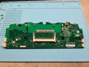
The mainboard is fairly sparse on the topside with the SODIMM slot and internal connectors taking up most of the real estate.
-
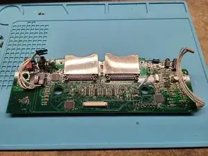
The bottom is a lot denser. The two CF card slots and their driver chips take center stage, flanked by the rest of the IO.
-
-
-
Now that we can finally access the battery. Two screws hold it in, and it lifts right out.
-
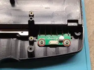
The board holding in the display pogo pins is also accessible with another two screws.
-
-
-
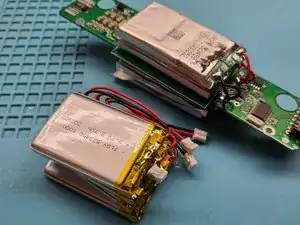
With the battery out we can take a closer look. That hole doesn't look so great, and probably has something to do with this not holding a charge.
-
The pack consists of standard 3.7V lithium cells in a 1S4P configuration. Capacity is not marked, but cell dimensions are 5.2x34x59 mm or 523459 in industry sizing.
-
I found some 523450 cells to rebuild the pack, which seem to work for now though capacity isn't great.
-
Note that rebuilding battery packs comes with the risk of personal injury, fire, and general bad juju, so read up on Li-Ion safety and pack construction before rebuilding your own.
-
-
-
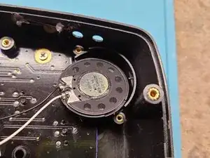
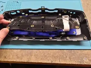
Now we return to the keyboard assembly we set aside earlier. The keyboard itself is sandwiched between the upper housing and speaker assembly.
-
With the removal of two screws, the speaker can be pulled free and give us access to the board.
-
-
-
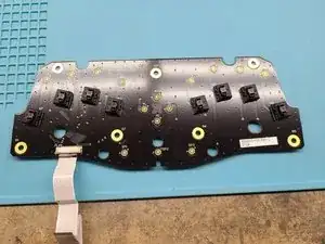
Seven screws hold in the keyboard itself, and once these are removed the board can be lifted free.
-
Flipping the board over reveals an interesting mix of switches. The braille dots are linear Cherry ML switches (also used on BrailleNote devices), but other buttons are conductive pads embedded into a rubber dome sheet.
-
The Cherry MLs would typically have a linear feel, but the dome sheet gives them a squidgy quasi-tactility. Funky!
-
-
-
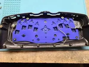
All that's left in the housing now is the dome sheet and microphone.
-
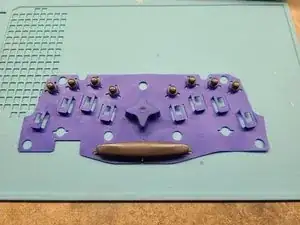
The dome sheet simply lifts out and the small keys stay attached to it. The braille keycaps will come out individually, but they're interchangeable, so no need to worry about which key was which.
-
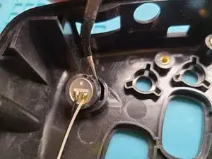
And finally the microphone. It's a friction fit in a rubber sleeve, so gentle prying with a spudger helps free it.
-
-
-
That's all folks! Hope you enjoyed a peek inside this little device.
-
Some parts, like the omnipresent nutserts (no screws into plastic here!) and modular construction really impressed me, others, like the just good enough for text to speech speaker and the dorky battery setup less so.
-
Either way, it's been a neat look into the world of older accessibility tech.
-