Introduction
Teardown of an Epson EB-575 Projector - it was having issues with the image being splotchy and dull - it shows the root cause of the problem, however I was unable to fix it and ended up throwing one of the LCDs out of alignment. So it ended up in a worse state than when it started.
Couple notes: There's some writing on the images where I was taking notes for where all the screws went. I'm sad I couldn't fix the projector, but figured I should upload this as a record for anyone else feeling brave enough to have a go.
There's a warning part way through about the point of no return - heed it well, if you're brave enough to continue, read the whole thing before you even start.
This particular model is the Epson EB-575Wie - Wireless Interactive Education Edition. The other versions of this projector should be very similar.
It is also known in some other countries as the Epson PowerLite 575W
-
-
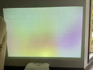
I grabbed this projector from work as it had been replaced as it had coloured marks over the screen making it difficult to use in a classroom.
-
General consensus from the internet is that either the polarisers have got dust on them, or they've got too hot and it's burnt the coating off them.
-
-
-
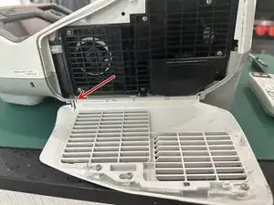
Remove the filter and the filter door. The door you can take off by flexing the plastic as marked.
-
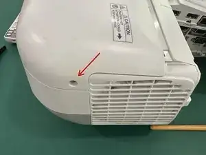
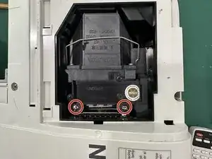
Remove the bulb cover by taking out the captive screw to get the cover off.
-
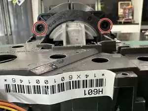
Remove the Bulb by taking out the two captive screws and pulling it upwards to get it out.
-
-
-
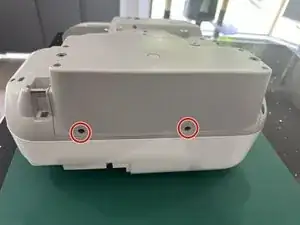
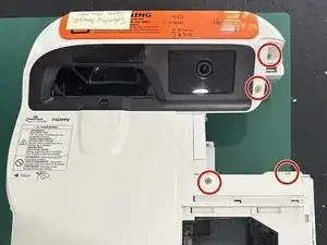
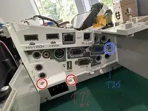
Remove Two Back screws - These are 3x6mm Black Machine Screws
-
Remove the 6 - 3x11mm Plastic Tapping Screws
-
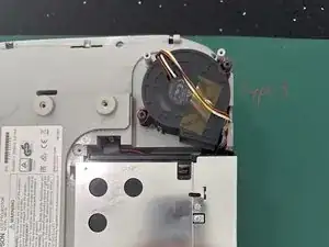
If you want to clean the fan, there's 2 - 30mm Plastic Tapping screws holding it in.
-
-
-
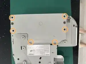
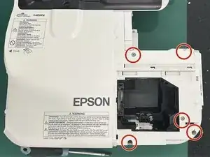
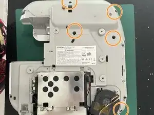
Remove 5 - 3x11mm Plastic Tapping Screws from the back
-
Remove 7 - 3x11mm Plastic Tapping Screws from the top
-
Not Pictured - There's one extra screw in the air filter intake to remove.
-
-
-
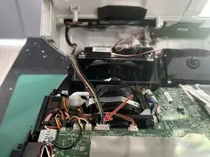
There are 4 cables connecting the top and bottom halves.
-
Once the 4 cables are disconnected you can remove the top case
-
-
-
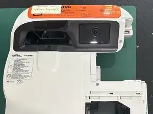
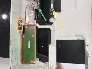
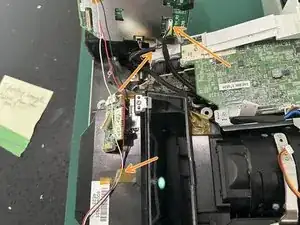
This is the EB-575Wie Version, so it has interactivity and education features.
-
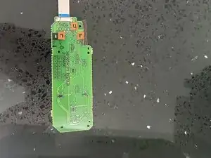
This is the Control Board with the buttons. Note the education version doesn't have buttons, but there's a PCB there still with no buttons soldered on.
-
This is the IR Remote Sensor
-
The other two arrows are IR Blasters for the interactivity and one to detect if something is infront of the lens (a safety feature)
-
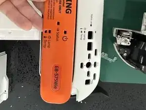
The education version has an orange plate that sits ontop of where the buttons would be.
-
-
-
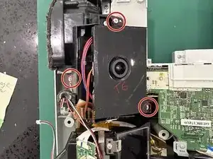
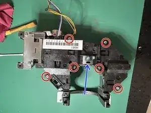
You need to remove the camera module to get the main board out.
-
3 Screws - 2x8mm Plastic Tapping
-
2 Cables to disconnect, the third is held down by a piece of kapton tape (it was connected to the top case)
-
-
-
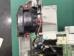
You don't have to remove the speaker to get to the rest of it
-
Unscrew the 3 screws holding the speaker in - 2x8mm Plastic Tapping Screws
-
Undo the screw holding the USB Cable down (it also connects to the speaker) - 2x10mm Plastic Tapping with a Washer
-
Unplug the Speaker and remove
-
-
-
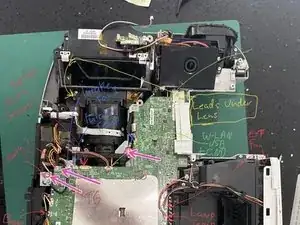
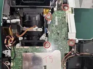
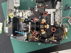
This is all the wiring that goes into the mainboard - I've IDed most of them.
-
While you're here - remove the WLAN Grounding Screw (2x6mm Wide Head machine screw), the Weird little metal bit held in by the same type of screw and the big grounding one (2x8mm Plastic Tapping Screw)
-
-
-
This side panel is way easier to just slide out with the mainboard - so it's best to just unscrew it now so it doesn't hamper later efforts!
-
Remove the 2 screws from near the IEC connector - 2x10mm (or may be 2x8mm - I got these mixed up first time I pulled it apart so I'm not sure! either fits)
-
Remove 1 screw from near the VGA port - 3x6mm Silver Coloured
-
-
-
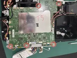
Remove 7 Screws from the mainboard - 2x6mm Wide Head Machine Screws
-
Don't lift up the mainboard just yet! See next step.
-
-
-
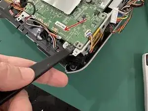
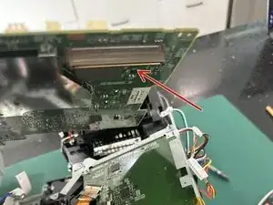
There's a connector underneath the mainboard marked with the arrow
-
Use a spudger to gently lift up as close as you can to the connector to pry it loose. It shouldn't require too much force.
-
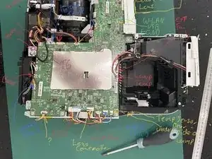
This is the top
-
This is the bottom
-
-
-
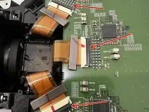
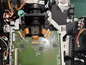
This is the board that talks to the LCD panels
-
Flick up the lever (Black part of the connector) on the Red/Green/Blue ribbon cables and gently slide them out.
-
-
-
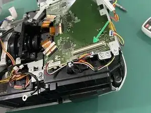
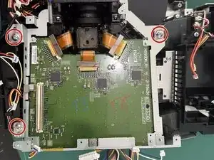
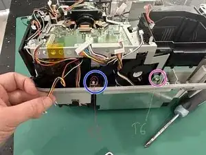
Remove the 3 3x7mm Wide Head Plastic Tapping Screws from the top
-
Remove the one 6x2mm Wide Head Machine Screw from near the lens
-
From the back remove the two marked screws. The Blue marked one is 2x6mm Wide Head Machine Screw. The Purple one is 2x8mm Plastic Tapping Screw
-
Carefully Lift the second mainboard up and out
-
-
-
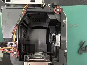
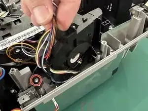
Remove the two screws holding the lamp cover in place and pull it off. 2x8mm Plastic Threaded Screw
-
Take note of how the cables from the fan are wrapped through it - this just keeps them out of the way when it's assembled.
-
-
-
Undo 4 marked screws - 3x11mm Plastic Tapping
-
Undo little screw holding an earthing plate near the curved lens - 2x8mm Plastic Tapping Screw
-
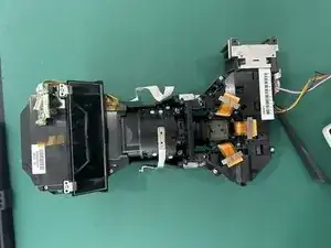
Lift the whole light path up, take note of the focusing slider, you can carefully maneuver it out past it without having to remove it
-
-
-
Remove the 2 Screws from the Top and 2 from the Bottom holding the Light Prism from the main lens
-
-
-
I'm just making up words now... This is the part just after the bulb where it goes through a bunch of mirrors.
-
Remove the 6 Screws - 2x10mm Plastic Tapping
-
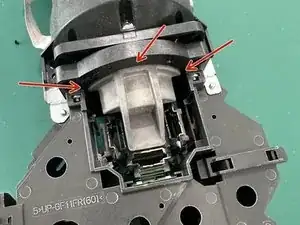
Carefully lift up the top - there's a lens attached to the top piece (Blue Arrow) - don't scratch it on your way out!
-
Take note of the orientation of the lenses - take a photo before you touch anything and note the little marks on the top of some of the lenses (or maybe put a little dot of marker on the top?)
-
-
-
I forgot to get a photo of this part - once you've split off the other part from this, the grey metal piece pictured has 3 screws holding it on.
-
-
-
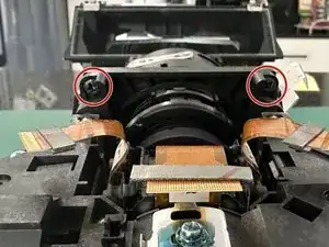
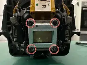
Remove the 4 Screws - 1x7mm Machine Thread
-
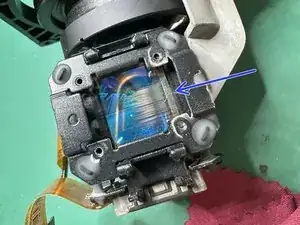
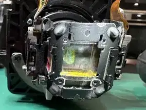
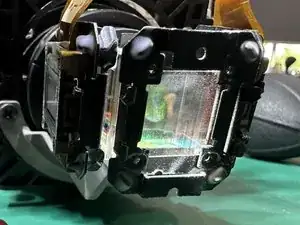
The second pic (Blue Arrow) is one I haven't touched yet. It shows where the Polariser has been scratched all the way up. This is either due to heat, or dust from the fans running up the polariser and damaging it on its way past.
-
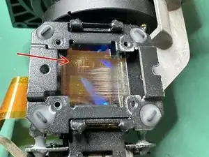
The third pic (Red Arrow) I tried to clean with a cotton bud - Note the tiny scratch marks. It didn't have any effect on the pre-existing scratch marks.
-
-
-
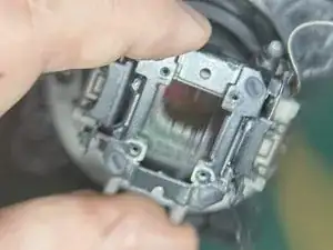
Here are some more photos of the damage to the polarisers. 2 of the 3 had severe lines up it like the images show. One was sort of OK.
-
My best guess is that this damage is caused by particles of dust being blown up across the polariser, eventually digging into and damaging the surface
-
The polariser is glued in as part of it being aligned in the factory. In terms of getting a replacement you would likely have to get all 3 LCDs + Polarisers pre assembled and calibrated to replace this part.
-
-
-
To reassemble, follow the steps in reverse!
-
Make sure you don't get any of the wires stuck under the mainboard when you put it back, or you'll have to take it back out again...
-