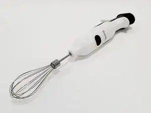
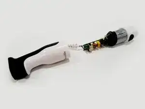
Introduction
-
-
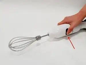
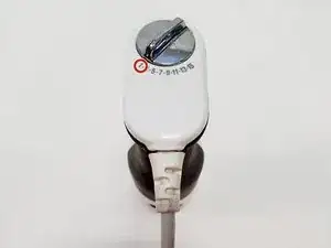
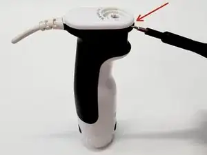
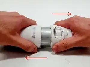
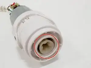
Press the eject buttons to release the attachment from the motor body. With this done, pull the lowest casing away.
-
-
-
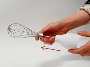
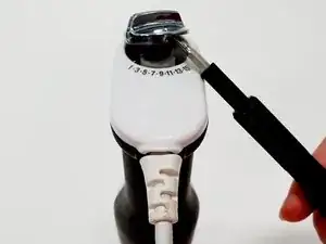
Turn the speed dial all the way down to number ‘1’. Now, using a flathead screwdriver, lever off the dial using the edge aligned with the number ‘15’ as the pivot point.
-
-
-
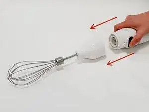
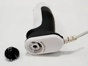
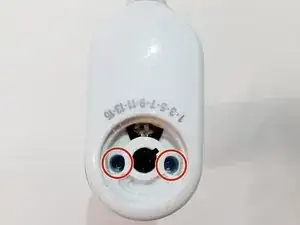
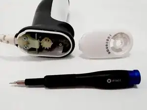
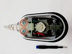
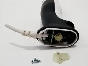
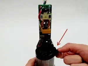
Remove two screws fixing the top case to the body with the screwdriver and pull the casing away from the motor body.
-
-
-
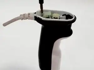
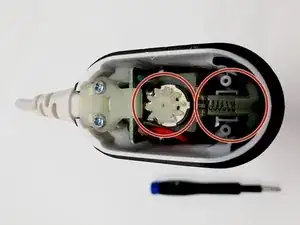
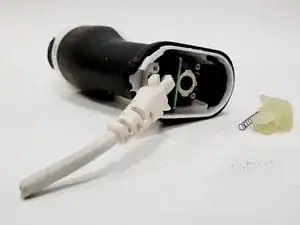
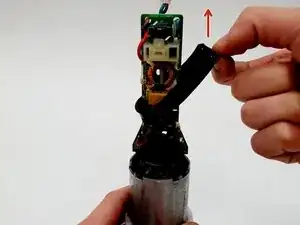
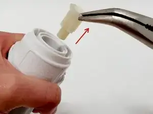
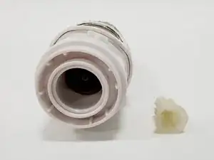
The trigger mechanism consists of a nylon component and a spring. No tools are required to remove this part and you can pull it out with your fingers. The same goes for the spur gear which simply slides out.
-
-
-
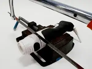
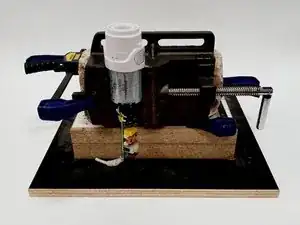
In production, the top casing is glued to the bottom casing. For this reason, the casing needs to be sawn apart. Clamp the top casing in place so that it does not slip. (See the attached photographs for an example of a clamping setup.)
-
-
-
Proceed to saw all the way around the top casing, approximately 5mm from the button. If done correctly, the smaller component should slide off, taking the motor and circuit board with it. You may need to employ a twisting and pulling action.
-
-
-
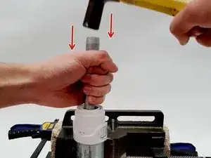
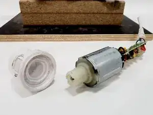
Set up the motor and remaining casing in a vice as shown in the picture. Take the dowel and place it in the opening of the remaining casing, and rest it on the metal whisk driver. GENTLY hammer downwards on the dowel until the motor falls through.
-
-
-
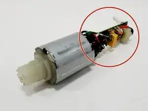
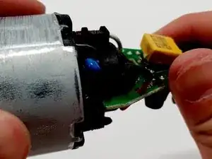
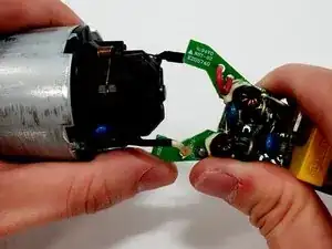
The circuit board is slotted into two grooves on the motor. Use one side of the circuit board and your thumbs as a pivot point to lever off the opposite side of the board. (See the photo for reference). The other side should now come away easily.
-