Introduction
This guide will take you through partially disassembling the lens, allowing you to access whichever major part or assembly you need (ex: autofocus assembly, zoom assembly, etc). This guide will not include taking apart the zoom assembly.
A dust blower is recommended to blow dust off of any internal lens elements or parts during this process. Additionally, a clean microfiber cloth is good to have incase you accidentally touch any of the internal lens elements and need to clean off your fingerprint from the lens.
There will be many small screws that must be removed from the lens. Many of the screws will be of different sizes. Please be sure to keep the screws in a safe place and keep track of where each one came from.
-
-
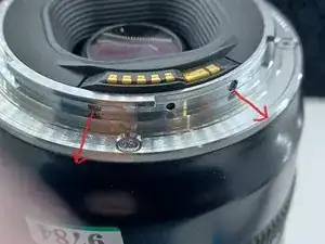
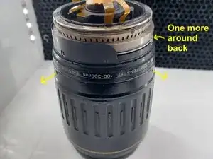
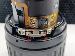
Remove the 2 screws on the side of the lens mount, holding in the contact assembly.
-
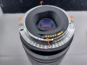
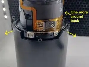
Next, unscrew the 4 screws holding the lens mount onto the lens.
-
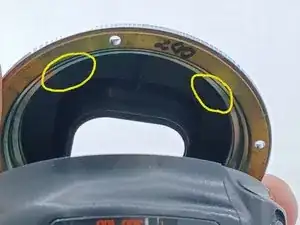
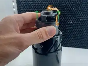
Carefully lift up one side of the lens mount (side opposite of the lens contact). Push the black plastic cover out of the lens mount. Take note that there are 4 plastic clips around the cover. These clips can break easily if you're not careful.
-
Push the lens contact off of the metal lens mount and set the lens mount to the side.
-
-
-
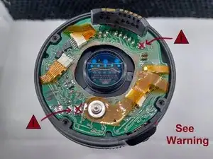
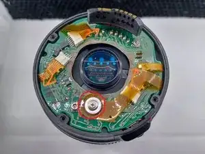
Unscrew the ribbon cable that is screwed down to the main PCB board.
-
Disconnect the remaining 3 ribbon cables connected to the main PCB board.
-
Remove the main PCB board and set it aside.
-
-
-
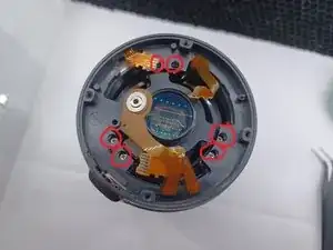
Unscrew the 6 screws holding in the fixed barrel.
-
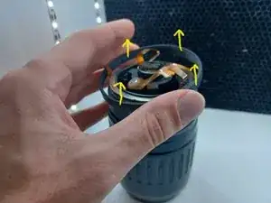
Remove the fixed barrel, being careful of the ribbon cables.
-
Pull off the focus ring.
-
-
-
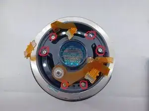
Take out the 6 screws holding in the top of the autofocus assembly.
-
Unscrew the 3 screws outside of the zoom ring.
-
Carefully pull off the autofocus assembly.
-
-
-
Unscrew the 2 screws holding on the zooming key.
-
Take off the zoom ring.
-
Unscrew the 3 screws holding in the zoom assembly.
-
Remove the zoom assembly from the front lens assembly.
-