Introduction
Tools
-
-
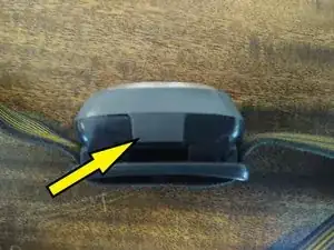
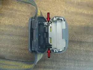
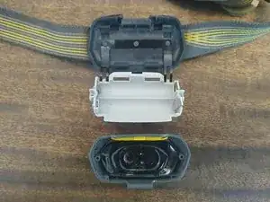
Open the case by lifting the tab and pushing the pieces of the case apart. The front of the case is latched to the rear with two flexible plastic straps, indicated by the red arrows.
-
-
-
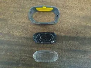
The front of the case breaks down into three loose pieces: the outer shell, a clear outer cover, and an opaque inner cover. A flexible, yellow switch cover fits into the outer shell.
-
-
-
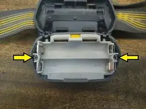
Separate the battery holder from the headstrap by pulling each plastic strap up over its catch on the battery holder.
-
-
-
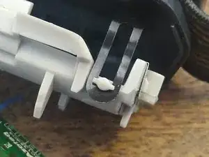
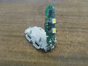
The PCB latches to the battery holder with two thin metal tabs. These tabs hold the PCB and battery holder together and make the electrical connection for the battery power. To separate the PCB and the holder, lift the PCB up 90 degrees and slide the latches out of the holder.
-
-
-
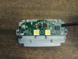
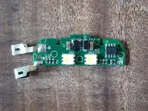
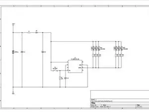
On the top side, battery power routs through an inductor and diode, then feeds a driver IC (U1). U1 drives two RGB LED packages in parallel. It also has a switch detect input. U1's part number is Azoteq IQS753. Note that Azoteq also fabricated the bare board and presumably assembled the PCB.
-
-
-
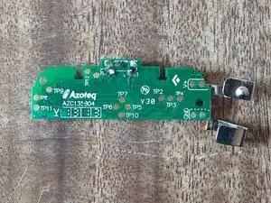
The bottom side faces the battery holder. The only component on this side is the switch, S1. The switch actuator points toward the top of the picture in this view. S1 failed on this headlamp and was removed.
-