Introduction
The AST Ascentia 520i is a notebook computer that was marketed by AST Computers, LLC, during 1999. The computer that we are tearing down was manufactured in Taiwan in the second half of 1999, based on the date codes printed on its circuit boards and integrated circuits. This notebook has the following specifications:
- 12.1" 800×600 active-matrix CCFL-backlit TFT TN LCD display
- Intel AGPset FW82443BX northbridge and PCIset FW82371EB southbridge
- Mobile Intel Pentium II "Dixon" 333 MHz CPU with 256 KB on-die L2 cache in µPGA1 615-pin package (SL3HK)
- 64 MB SDRAM (32 MB on the motherboard and 32 MB on the SO-DIMM). Has only one SO-DIMM slot.
- 4.3 GB 4200 RPM hard drive (Toshiba MK4309MAT). Hard drive assembly can be removed without tools. Supports 2.5" IDE hard drives up to 9.5 mm thick.
- Removable media bay that can accommodate a CD-ROM drive or 1.44 MB floppy drive. This notebook only came with the floppy drive.
- Silicon Motion LynxE integrated graphics with VGA output (and possibly a composite video output, but ours didn't have it)
- Conexant Riptide RACC010 sound card with headphone/line-out jack, microphone jack, and built-in 56K modem
- Built-in stereo speakers
- One Type I/II PC Card slot controlled by an O2Micro OZ6812 Challenger PC Card controller. Most other contemporary laptops had a pair of PC Card slots that can hold up to two Type I/II PC Cards or one Type III PC Card.
- One of each of the following ports: USB 1.1, 25-pin parallel, 9-pin serial, PS/2 keyboard/mouse, infrared (IrDA), and docking station.
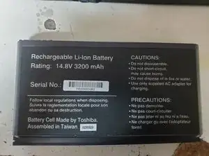
- Removable 14.8V 3200 mAh eight-cell lithium-ion battery
- Dimensions:
- 1-1/8" thick (open); 1-9/16" thick (closed)
- 11-1/8" wide
- 8-3/4" deep
- Weight: 5.2 lbs (with battery and floppy drive but without AC adapter)
We are tearing down this notebook because we were not able to find even a single piece of information on the Web about that specific model of computer, despite being sold by a major computer company at the time. However, this notebook also had another model number (3882A452) which was used by CompUSA for its Amerinote RL366C notebook.
-
-
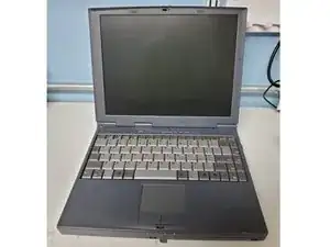
This is the notebook that we will tear down.
-
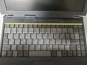
On the palmrest, there are the United States QWERTY keyboard with built-in numeric keypad and Num/Caps/Scroll Lock LEDs, a two-button trackpad, and the power, sleep, and Internet (WWW) buttons.
-
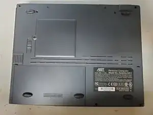
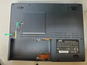
On the bottom, there are the RAM cover, battery, and removable media bay latch.
-
-
-
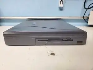
Right side: Removable media bay (currently holding a 1.44 MB floppy drive) with infrared sensor on the bottom-right.
-
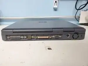
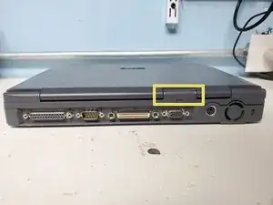
Rear side: (left to right) Parallel port, serial port, docking station port, VGA port, PS/2 keyboard/mouse port, fan, and Kensington lock slot.
-
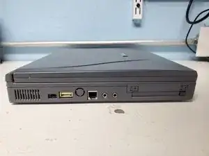
Left side: Charger port, USB port, knockout for a composite video output, RJ-11 modem port, microphone jack, headphone/line-out jack, and PC Card slot.
-
On the 3-pin charger port, the outer pins connect to ground and the center pin takes a 20.5V DC input at 2.5A.
-
-
-
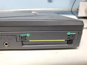
Slide the two latches toward the middle of the battery to disengage them. Then grip the battery with your hands, slide it toward you to disconnect it, and lift it from the battery compartment.
-
-
-
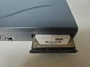
Slide the two latches on opposite sides inward to disengage them, then grip and pull the lower edge of the hard drive assembly (located on the yellow line) to release it from the bay.
-
-
-
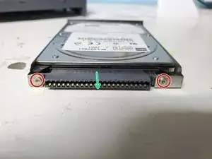
Remove the four screws (two on each side) securing the hard drive assembly to the bracket, and also remove the two screws (one on each side) securing the interposer to the bracket.
-
Once the screws are removed, take out the hard drive from the bracket and gently extract the interposer from the hard drive.
-
-
-
Move the latch toward the back of the laptop, then while holding onto the grooved section of the removable media drive, carefully remove it from the bay.
-
If you cannot pull it out, you can insert a spudger into the vertical gap next to the grooved portion (indicated by a yellow line) and gently twist the spudger to free it from the bay.
-
-
-
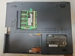
Remove the screw securing the memory module door, and then carefully pry and lift off the door.
-
Disengage the two clips (located on opposite sides) holding the memory module to release it from its slot.
-
-
-
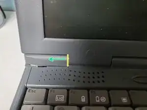
Wedge a spudger in the vertical gap (shown by a yellow line) and twist it outward to free the hinge cover.
-
Note: The hinge covers are identical.
-
-
-
Gently insert the spudger into the gaps around the area of the cover concealing the display assembly cables. Next, open the laptop and gently insert the spudger into the gap nearest to the top row of the keyboard to detach the button cover.
-
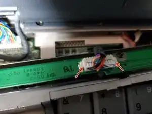
To disconnect the button cover from the motherboard, carefully pry each side of the cable's connector from the connector on the button board.
-
-
-
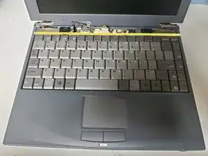
After removing the button cover, grasp the top edge of the keyboard and gently flip the keyboard toward the display.
-
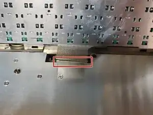
Use a spudger to gently unlatch the ZIF connector connecting the keyboard to the motherboard, and lift the keyboard.
-
-
-
Remove the seven screws (circled in red) securing the CPU heatsink to the palmrest, and then lift off the heatsink.
-
Note: The heatsink has built-in thermal pads that are placed on the CPU and chipset, so you will not need to use thermal paste.
-
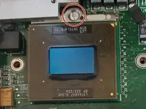
Use a flathead screwdriver and turn the CPU retaining screw 180° counterclockwise to loosen the CPU from its socket.
-
Gently lift the CPU from the socket.
-
-
-
Remove the four screws securing the display assembly hinges to the palmrest.
-
Carefully and slowly open the laptop, and then disconnect the two cables connecting the display assembly to the motherboard.
-
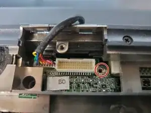
One of the cables (the LCD data cable) is connected to an interposer board which is secured by a screw. To remove the other cable (the inverter cable), disconnect the interposer board first.
-
Lift the display assembly from the base of the laptop.
-
-
-
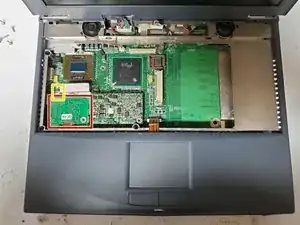
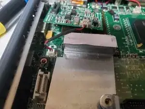
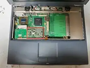
To remove the modem board, gently pry it from the motherboard, and then disconnect the wire that connects it to the RJ-11 jack on the motherboard. Also remove the heatsink underneath.
-
To remove the VRM (voltage regulator module) board, gently pry it from the motherboard.
-