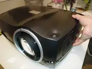
Introduction
The GP3 series includes other projectors including the commercial/professional models F3, F30, F32, F35, FL32 and FL35 (LED light source), and is similar to the consumer/home theater models Action! model three, cineo3, and some Avielo models. They were available in native resolutions including SXGA+ (1400x1050), FHD (1920x1080), WUXGA (1920x1200), and WQXGA (2560x1600).
The factory specifies service intervals for the fans (every 8,000 hours) and color wheels (every 16,000 hours). In this guide, we will disassemble this F35 projector enough to reach all of these service-replacement items. In total there are 6 fans and two color wheels:
- 1x Main blower fan (~6")
- 1x DLP chip (DMD) PCB blower fan (~2")
- 2x Lamp blower fan (~1.5")
- 2x Lamp driver PCB fan (3")
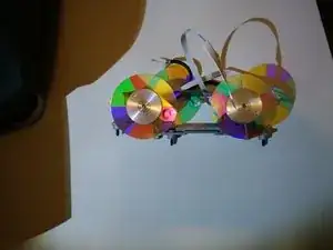
- 2x VizSim Bright color wheels
-
-
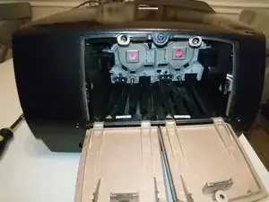
Each lamp has a separate door. Unscrew the captive Philips screw at the top of the door and open it.
-
-
-
Observe there are 3 plastic thumbscrews per lamp -- two on top and one at bottom.
-
Rotate them 1/4 turn (90 degrees) counter-clockwise to unlock.
-
If they are difficult to turn by hand, a large flat-head screwdriver may also be used.
-
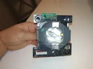
Once all 3 screws are unlocked, grasp the lamp housing from the rear protrusion, and pull. If you feel a lot of resistance, try wiggling the screws to ensure they have released.
-
-
-
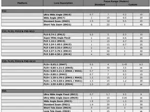
EN41 Standard Zoom Lens Throw Ratio 1.69:1-2.50:1
-
EN43 Wide Zoom Lens Throw Ratio 1.20:1-1.69:1
-
EN44 Short Tele Zoom Lens Throw Ratio 2.50:1-4.61:1
-
EN45 Ultra Wide Zoom Lens Throw Ratio 0.80:1-1.21:1
-
-
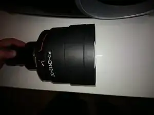
-
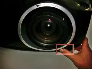
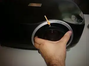
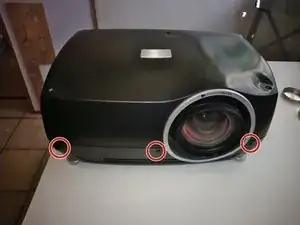
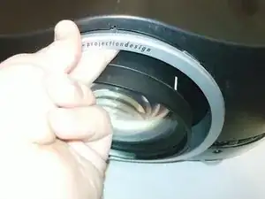
Begin by pressing and holding the lens-release button with your right hand (or have a helper do this).
-
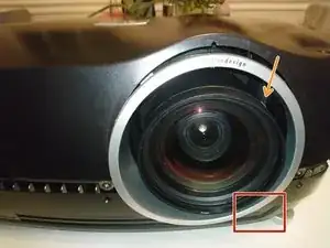
Grasp the outside barrel of the lens with one or two hands, and start to rotate it counter-clockwise. Be prepared to support the weight of the lens as it is released from the locking mount.
-
It will rotate about 45 degrees -- watch the mark on top of the pictured lens for the start and end points.
-
After rotation stops, slide the lens out of the projector.
-
-
-
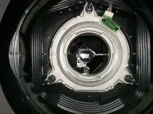
Before installing a lens, make sure there are no obstructions inside the projector (like the original plastic lens mount protector), and remove any back cover or rear cap on the lens itself.
-
Look at the metal mounting flange inside the projector, and at the tabs on the lens itself. There should be three tabs/slots visible.
-
Two tabs/slots are about the same size -- they'll be on top when the lens slides in.
-
One slot/tab will be about 2/3 the length of the others. That one goes "down" as the lens is inserted.
-
Insert it such that the smallest tab of the lens mount "foot" faces down, make sure the lens is completely seated "in-plane', then gently rotate clockwise about 45 degrees -- you should hear and feel a definite tactile click when it locks into place.
-
-
-
After removing bulbs and lens, we finally get to open up the projector.
-
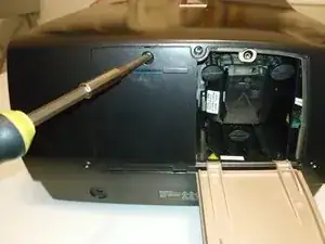
There are 11x T10 screws holding the upper case on.
-
3 on the right (lamp) side
-
2 on the left (power) side
-
3 on the rear
-
3 on the front (see pic on next step)
-
-
-
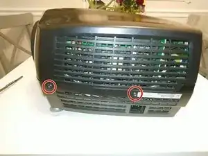
Here are the last screws, on the front: 3x T10
-
After all the screws are removed, start lifting the case from the left and right side.
-
-
-
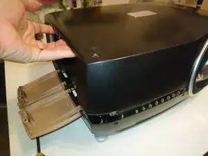
The shell may resist being lifted off. Wiggling it gently will help, but it may also be catching around the silver lens shroud, which is a separate part.
-
-
-
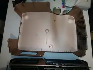
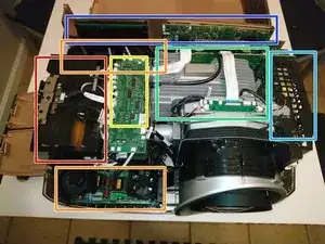
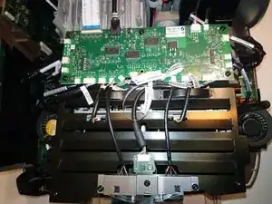
The inside of the plastic shell has a metallic coating, which gives an attractive shiny copper sheen. Set the lid aside for later -- let's get our bearings inside!
-
Lamp house (2 lamps inside)
-
Lamp driver (1 for each lamp)
-
Light path -- color wheels and combining prism -- under this PCB
-
Image engine (including DLP device)
-
Power supply
-
Rear I/O panel and LCD
-
-
-
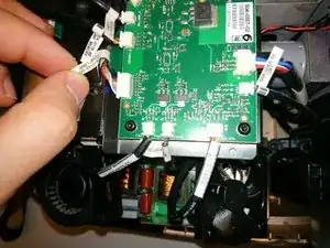
To reach the color wheels, we must remove the lamphouse cover. This PCB doesn't actually have to be removed, but all the wires going to it must be disconnected.
-
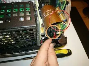
PD was very considerate in manufacturing these projectors -- there are labels on the cable and on the PCB connector.
-
Starting at the large ZIF ribbon cable, and naming them clockwise, we have: IO card ribbon cable, DC POWER IO, Fan Main, IR, Fan Ctrl VDI, Fan Lamp Driver, [lamp blower fan], Temp Lamp, Lamp Memory, Lamp 2 (switch), CW2, color wheel 2 ribbon, color wheel 1 ribbon, CW1, Lamp 1, Lamp Memory, Temp Out, [lamp 1 blower fan], Fan Lamp Driver, LMP Ctrl VDI, IR2
-
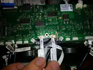
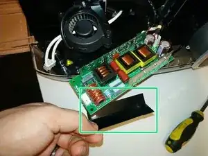
Well, most of my cables were well-labeled. Some, though, are close together enough and similar enough to possibly be confused. So, I suggest labeling connector and cable with marker to distinguish them. See example in pic 3 -- these are ribbon cables for the color wheel motors, and the 3-wire connectors for the position sensors.
-
-
-
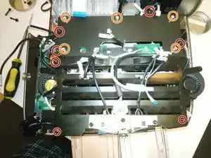
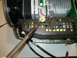
There are 2 ventilated metal covers here, held down by 7 screws total. The IO PCB does not have to come out, but makes it a little easier to reach the screws.
-
4 screws in the color wheel /light path cover (at the top in the photo), and 3 in the lamp house cover (at bottom in photo).
-
If you choose to remove the IO PCB entirely, these 5 standoffs are where the PCB screws go.
-
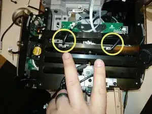
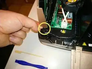
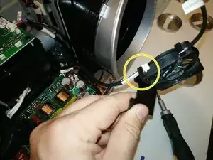
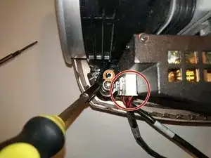
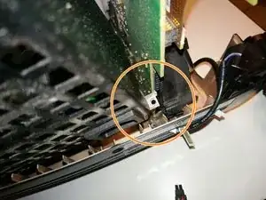
As you lift off the lamphouse cover, carefully work around these two wires -- for the lamp hour chip readers. They connect to boards below the cover -- it's probably better to leave them connected to the IO PCB, and unplug the connectors circled here instead.
-
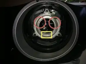
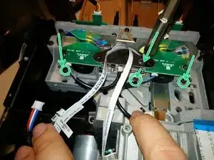
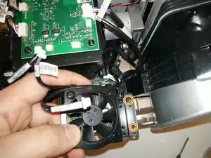
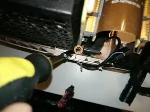
The color wheel bracket is held down by just 3 T10 screws -- but they're about 14mm long and tricky -- especially the middle one, where you must reach through a hole in this black plastic gusset. I suggest using screwdriver with a magnetic tip here.
-
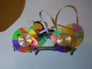
Once these 3 screws are removed, the color wheel bracket will be wobbly and loose. Lift it up carefully -- the wheels are very thin optical glass.
-
-
-
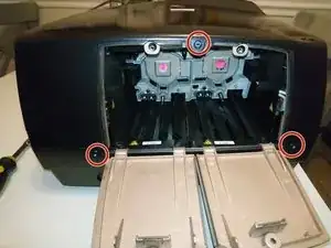
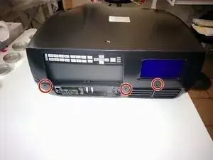
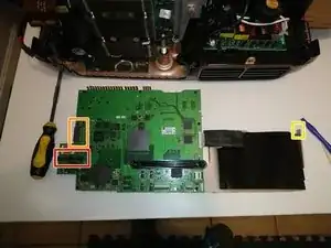
The video and control inputs, buttons, and LCD display are all part of one assembly. To remove it:
-
This brown ribbon cable handles all the data going to and coming from this board. Disconnect it gently from the rear panel - a plastic spudger tool can help with this.
-
There is a Molex-style power connector. Depress the lock tab, and pull it out.
-
Now, lift the interface board up. It might bind on the right side where it fits into a plastic tab on the projector bottom.
-
-
-
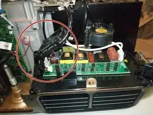
There are two lamp driver boards, one in the front and one in the back. These provide high voltage and starting current for the lamps. Each one has a square fan mounted to a bracket.
-
Remove 2x T10 screws holding each fan bracket.
-
Two cables are held in each fan bracket's cable clips. One is for the fan, but the other one needs to be disconnected and slid out from the clips.
-
The fans are held in their brackets with four plastic push-rivets. These can be pushed out from the back with a screwdriver or small punch -- if you are careful, they can be reused to mount the new fans.
-
-
-
The lamp driver PCBs do not have to be removed, but all wires need to be disconnected. Each board has:
-
A 2-pin low voltage connector from the power supply
-
A small 3-pin connector, on the vertical daughter board
-
A 2-pin white connector, carrying high voltage into the lamps.
-
If removing the PCB, each one is held by 4x T10 screws.
-
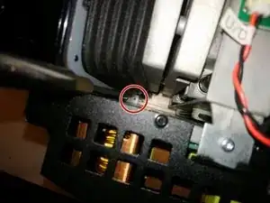
The front driver PCB has a plastic insulator on one of its mounting screw posts. Be careful to not lose it!
-
-
-
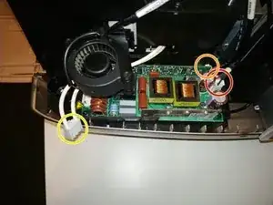
Disconnect 2 Molex-style power cables. If it's too difficult to reach them, wait until you've got all the screws out and are starting to lift the power supply away.
-
Undo 2x black T10 screws
-
Undo 1x silver T9 screw, at the top
-
There are a couple more notes before removing the power supply -- see next step.
-
-
-
There is a 4th screw tab on the power supply, but my unit had no screw here. Your experience may differ.
-
Tilt the power supply out slightly, to clear the bracket at the top, then slowly lift up to remove.
-
It may help to bend the plastic bottom shell of the projector away, gently, to help free the main AC power socket.
-
When lifting the power supply out, pay attention to the rear screw tab. It's sharp metal, and is very close to the back of a large PCB. Don't scrape it (or worse, knock small components off)!
-

To reassemble your device, follow these instructions in reverse order.
