Introduction
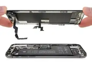
Prereq-only for detaching the display assembly.
-
-
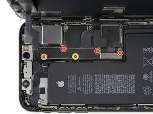
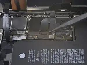
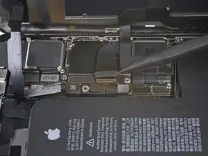
Remove five screws securing the logic board connector bracket, of the following lengths:
-
Three 1.0 mm Y000 screws
-
One 1.3 mm Y000 screw
-
One 3.7 mm Phillips screw
-
-
-
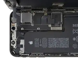
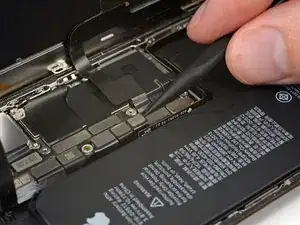
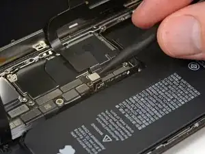
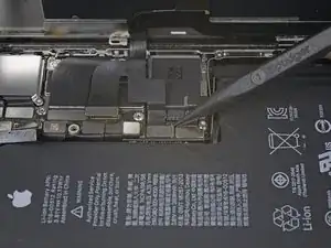
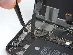
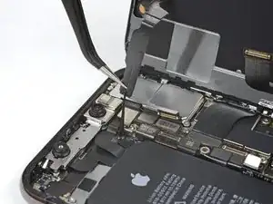
Use a spudger or a clean fingernail to pry the battery connector up from its socket on the logic board.
-
Bend the connector slightly away from the logic board to prevent it from accidentally making contact with the socket and providing power to the phone during your repair.
-
-
-
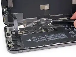
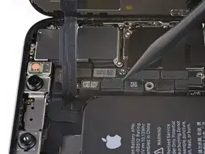
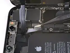
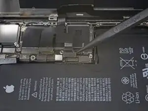
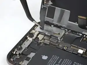
Use a spudger or a fingernail to pry up and disconnect the front panel sensor assembly connector.
-

Conclusion
To reassemble your device, follow these instructions in reverse order.

The ribbon makes the 1.3 mm screw a little tricky. Use one hand to hold the display at a 90 degree or smaller angle to create the slack necessary to get the screw driver in place.
charlotte -
I tracked my screws by using my kids fridge magnets to hold each screw size and placing a piece of masking tape below with the screw size.
charlotte -
I stripped a screw ugh
Tresia -
Where can i buy a One 1.3 mm Y000 screw
Ismail -
FYI: I used a tiny piece of scotch tape to hold those 1mm screws in place while aligning the magnetic screwdriver. Otherwise they are so tiny the magnetic bit pulls them right out the hole.
Jeff Miller -