Introduction
Follow the steps in this guide to remove or replace the LCD shield plate backing the display on an iPhone 7.
-
-
Power off your iPhone before beginning disassembly.
-
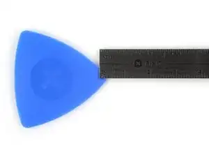
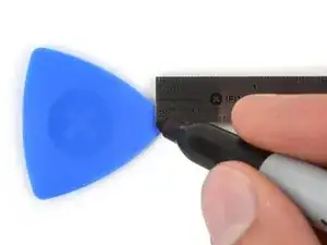
Remove the two 3.4 mm pentalobe screws on the bottom edge of the iPhone.
-
-
-
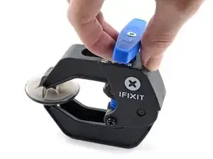
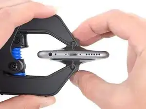
Pull the blue handle backwards to unlock the Anti-Clamp's arms.
-
Slide the arms over either the left or right edge of your iPhone.
-
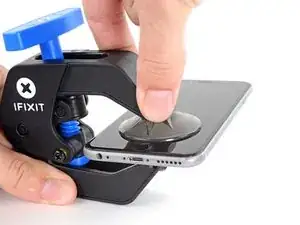
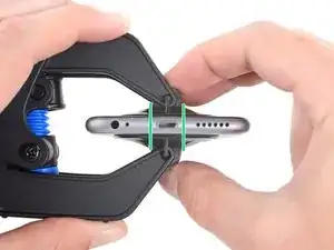
Position the suction cups near the bottom edge of the iPhone just above the home button—one on the front, and one on the back.
-
Squeeze the cups together to apply suction to the desired area.
-
-
-
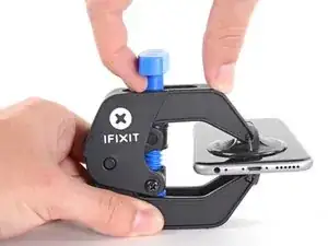
Pull the blue handle forwards to lock the arms.
-
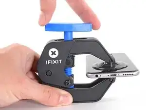
Turn the handle clockwise 360 degrees or until the cups start to stretch.
-
Make sure the suction cups remain aligned with each other. If they begin to slip out of alignment, loosen the suction cups slightly and realign the arms.
-
-
-
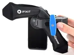
Heat an iOpener and thread it through the arms of the Anti-Clamp.
-
Fold the iOpener so it lays on the bottom edge of the iPhone.
-
Wait one minute to give the adhesive a chance to release and present an opening gap.
-
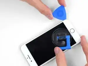
Insert an opening pick into the gap.
-
Skip the next three steps.
-
-
-
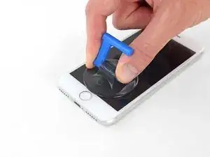
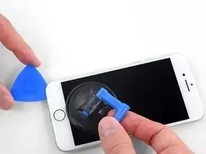
Heating the lower edge of the iPhone will help soften the adhesive securing the display, making it easier to open.
-
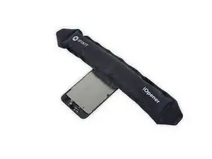
Use a hairdryer or prepare an iOpener and apply it to the lower edge of the phone for about 90 seconds in order to soften up the adhesive underneath.
-
-
-
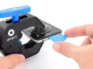
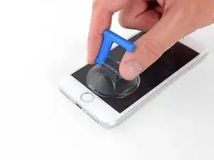
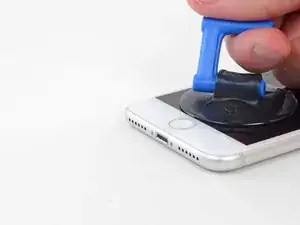
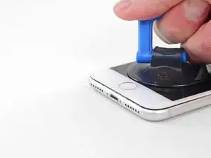
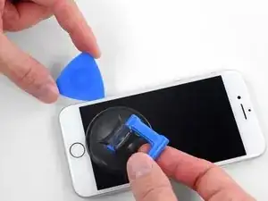
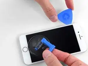
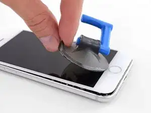
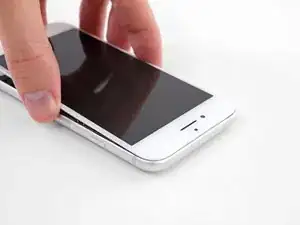
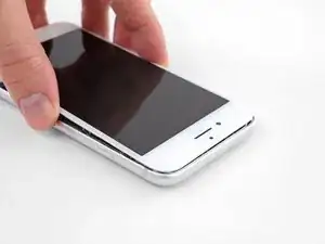
Pull up on the suction cup with firm, constant pressure to create a slight gap between the screen and the frame.
-
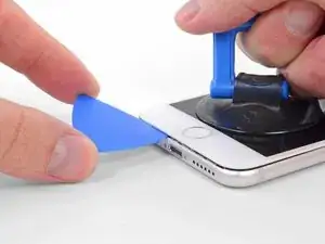
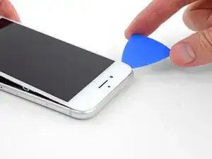
Insert an opening pick into the gap.
-
-
-
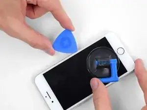
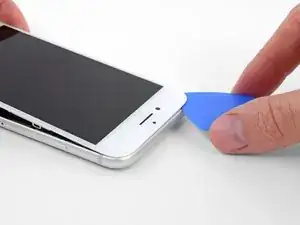
Slide the opening pick up the left edge of the phone starting at the lower edge and moving towards the volume control buttons and silent switch, breaking up the adhesive holding the display in place.
-
Stop near the top left corner of the display.
-
-
-
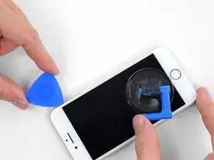
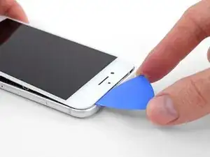
Re-insert your tool at the lower right corner of the iPhone, and slide it around the corner and up the right side of the phone to separate the adhesive.
-
-
-
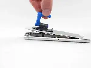
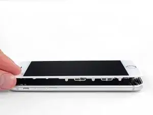
Gently pull up on the suction cup to lift up the bottom edge of the display.
-
Pull on the small nub on the suction cup to remove it from the front panel.
-
-
-
Slide an opening pick underneath the display around the top left corner and along the top edge of the phone to loosen the last of the adhesive.
-
-
-
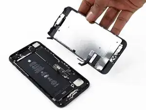
Slide the display assembly slightly down (away from the top edge of the phone) to disengage the clips holding it to the rear case.
-
-
-
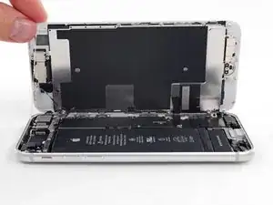
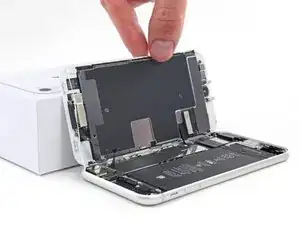
Open the iPhone by swinging the display up from the left side, like the back cover of a book.
-
Lean the display against something to keep it propped up while you're working on the phone.
-
-
-
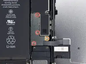
Remove four tri-point Y000 screws securing the lower connector bracket, of the following lengths:
-
Three 1.2 mm screws
-
One 2.4 mm screw
-
-
-
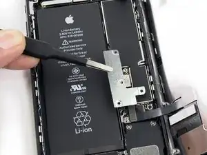
Use the point of a spudger to lift the battery connector out of its socket on the logic board.
-
-
-
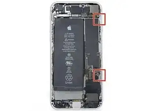
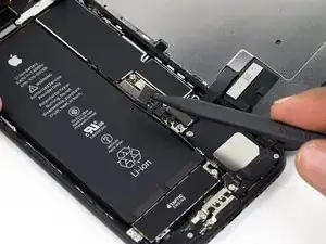
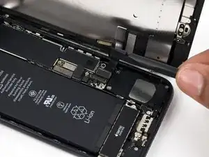
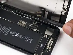
Use a spudger or a fingernail to disconnect the two lower display connectors by prying them straight up from their sockets on the logic board.
-
-
-
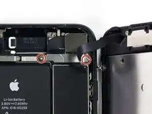
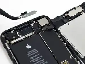
Remove the two 1.3 mm Phillips #000 screws securing the bracket over the front panel sensor assembly connector.
-
-
-
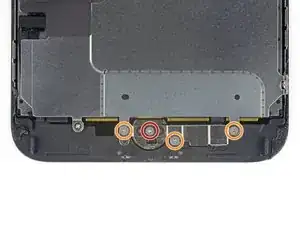
Remove the four Y000 screws securing the bracket over the home/Touch ID sensor:
-
One 1.1 mm screw
-
Three 1.3 mm screws
-
-
-
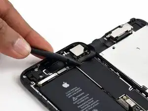
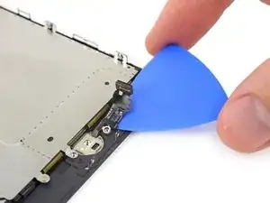
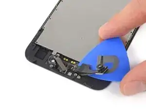
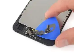
Pry under the left edge of the home button cable connector to disconnect it from its socket.
-
-
-
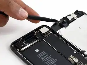
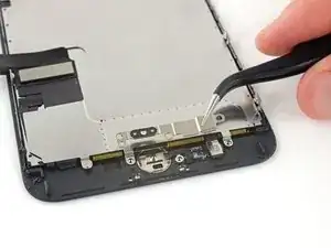
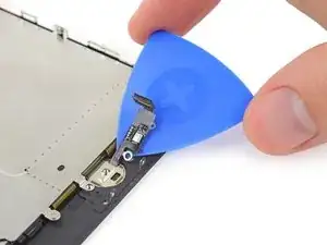
Carefully pry up the underlying connector and move it out of the way of the home/Touch ID cable.
-
If the connector doesn't pry up easily, use a hair dryer or iOpener to heat and soften the adhesive securing the connector, and then try again.
-
-
-
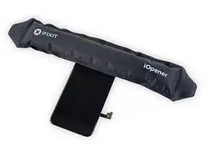
Flip the display assembly over. Use a hairdryer or prepare an iOpener and apply it to the lower edge of the display for about 90 seconds in order to soften up the adhesive underneath.
-
-
-
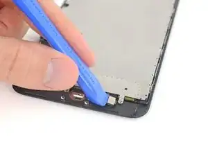
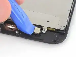
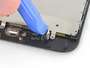
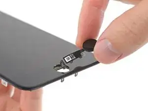
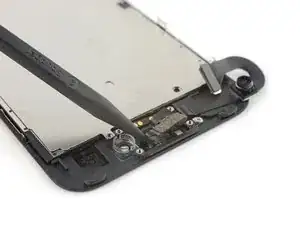
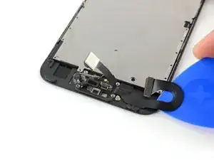
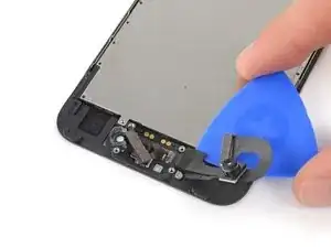
Use an opening pick to gently separate the adhesive holding the home/Touch ID sensor cable to the back side of the display panel.
-
-
-
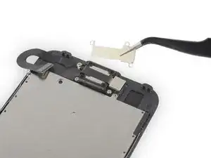
Remove the home/Touch ID sensor assembly by lifting it through the front side of the display.
-
-
-
Remove the three Phillips screws securing the earpiece bracket to the front panel:
-
Two 2.6 mm screws
-
One 1.7 mm screw
-
-
-
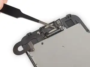
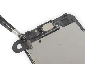
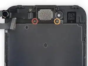
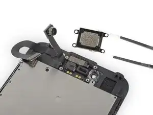
Remove the two Phillips screws securing the earpiece speaker to the front panel:
-
One 1.9 mm screw
-
One 2.5 mm screw
-
-
-
Reheat your iOpener and apply it to the upper edge of the display assembly to soften the adhesive holding the front camera and sensor assembly in place.
-
-
-
Slide the pick towards the front facing camera housing, separating the adhesive holding the cable to the front panel. Stop just before the screw posts.
-
-
-
Use the pick to lift the camera cable up off of the two plastic posts on the front panel and separate it from the last of the adhesive.
-
-
-
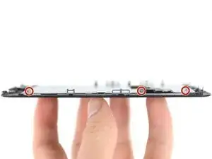
Remove the three 1.2mm tri-point Y000 screws from either side of the display assembly for a total of six screws.
-
-
-
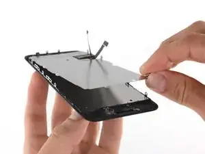
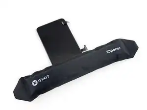
Heat an iOpener and lay it over the edge of the shield closest to the home button to soften the adhesive holding it in place.
-
-
-
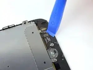
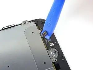
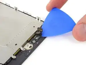
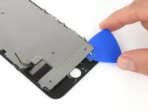
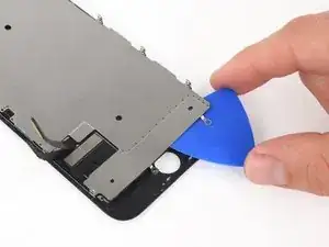
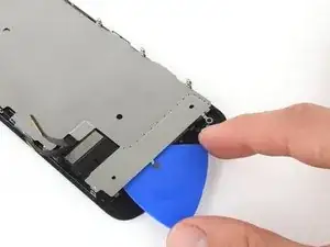
Use an opening pick to break up the adhesive near the home button that holds the LCD shield plate to the display assembly.
-


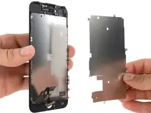
To reassemble your device, follow these instructions in reverse order.

6 comments
Awesome Guide! Very easy to follow!!! Thanks!
Use a good tri-point screwdriver for this repair. Some of the screws are very tight!
Absolutely true. The cheap Y000 driver that came with a repair kit was stripped to uselessness by the time I got to the shield screws.
I am a better technician because ifixit repair guide have made it easier for me. Thank you
Agba -
Can anyone confirm 7/7P's pentalobe screws have a ring of seal near the screw head?
Cooper Chase -
Confirmed, the screws have a black ring seal around the head.
rcheing -
Can’t get the display front
Bernadette Pfeifer -
From personal experience, I highly recommend before doing this procedure or any other, that you do a backup of your phone (preferably local) in case your procedure goes south.
ballina5ny -
I purchased the repair tools with the replacement battery from iFixit. The tools include a screw driver and three heads none were labeled 3.4 mm. I think the one that fit the pentalobe screws was labeled Y000. The guide should identify the screw driver head supplied by the kit not 3.4mm.
Mark Lieberman -
in the iphone 7 replacement battery kit from iFixit, the screwdriver that fits the 3.4 mm pentalobe screws is labeled P2 (and not Y000)
Jan-Tijn Oppermann -
3.4 mm is the height of the screw and is not related to the screw driver code.
Ahmad Vaziri -
the screwdriver PH000 does not work i wasted two screws and now they dont have the 4 cross mark they are now a circle, i buyed it all from Paraguay and it doesnt work, had to assembly back the parts because i got stuck like i mention with some screws, well im just going to send to a professional to install, thanks
Martin Frutos, Nuñez -
The bottom screws are Pentalobe, not Phillips.
Bram Driesen -
Before starting, I would recommend backing up your Iphone’s data just in case.
Jon Moylan -
If you managed to make it to this section, just send the phone into apple for 50 + 6 dollars shipping. The ribbon cables on the screen are designed to break. I can literally twist on the rest of the cable and it won’t fall apart but there is a diagonal section where it snaps. This is the fault of apple and the fault of ifixit for misrepresenting the fragility of the cables.
Ryan Huebert -
Had to reheat it a few times for a minute each with a hairdryer to get the seal to break after pulling and rocking the suction
Cynthia Lamb -
I’m technically challenged. Is there a premier national service who can professionally install a replacement battery got my 7 +?
Richard -
Do the screws come out in total?
YVES THEUGELS -
They may come out or may not. If you loosen as much as you can and they don't come out you should still be able to pry open the bottom. Once you get the screen off you can then push the screws out from the inside.
Anthony Falabella -
Is it the P2 you should use for the bottom??
YVES THEUGELS -
I heated the bottom of the phone with a hairdryer and then used a syringe to put a couple of drops of acetone directly into the bottom two screw holes. I GENTLY pulled on the screen with the suction cup and used the pry tool to GENTLY separate the screen. The sealant is applied around the entire display so be very careful pulling it off so you don’t break the fragile display cables.
Anthony Scaminaci -
At first it was very difficult to open, per instructions. I used a heat/ice pack and nuked it for 1 minute. The pry tool wasn’t working so I carefully used my pocket knife to wedge the cover open. The rest of the procedure went well until I cracked the glass while trying to get the top right corner to pop off. Other than that mistake, all went well. Tip: before setting the new battery, attach the battery connector first and leave enough room for the taptic engine, or better yet, place the taptic engine before adhering the replacement battery. This way you’ll have a small gap between the two, whereas mine barely fit. Good job on hosting the video, Gwendyl.
Klaus Preiss -
I love the fact that the screw bit and shaft are magnetic! I almost lost a screw and found it attached to the magnet.
I used a heat/ice pack and nuked it for 1 minute. At first the display cover was very difficult to open with the pry tool, per instructions. The pry tool wasn’t working so I carefully used the blade of my pocket knife to wedge the cover open. The rest of the procedure went well until I cracked the glass while trying to get the top right corner to pop off. Other than that mistake, all went well. Tip: before setting the new battery, attach the battery connector first and leave enough room for the taptic engine, or better yet, see the taptic engine in place before adhering the replacement battery. This way you’ll have a small gap between the two, whereas mine barely fit because I placed it almost too low.
Good job on hosting the video, Gwendyl.
Klaus Preiss -
I replaced the lightning connector assembly and reassembled. The old one did not 'click' into the cable and had corrosion inside, it needed the cable to be placed in a specific way to charge. The new part - does not recognize that a charger is plugged in at all.
I backtracked the assembly - took it apart, put it back again - and find that every thing on the part works - the mic, speakers, taptic engine.
The original problem with the cable still persists. Any ideas?
H K -