
Introduction
Fix your power button by following the steps in this repair guide.
Note: Steps are based on this guide.
-
-
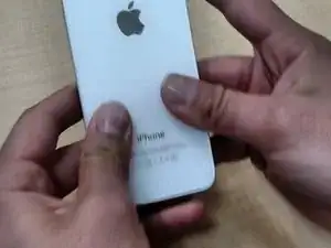
*Power off your phone before you start repairing
-
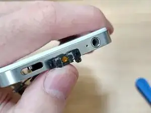
Remove the two small screws next to the dock connector
-
-
-
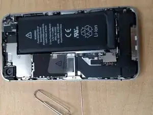
Carefully pull the rear panel away from the iPhone. Be careful not to break the clips that attach it to the phone.
-
-
-
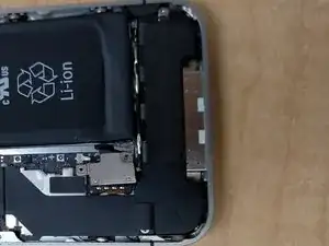
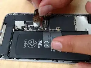
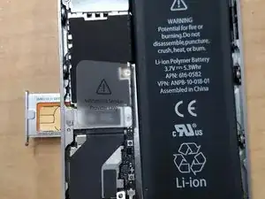
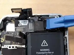
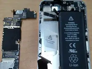
Remove the two screws securing the battery connector to the logic board
-
detach the battery connector from the socket, then lift the bottom side of the connector and by placing the head of the tool in the middle of the speaker and the metal connector.
-
-
-
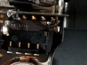
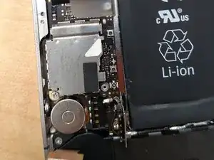
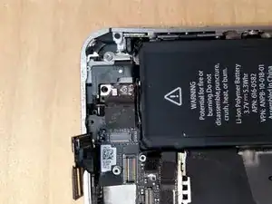
Use the head of your tool to carefully pull up the pressure contact which is located underneath the battery.
-
don't rip the battery connector socket on the logic board, this is an essential part of the iPhone connected by four soldered points.
-
-
-
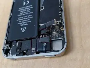
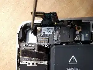
Unscrew the two screws securing the dock connector cable cover.
-
Once completed, Remove the metal dock connector cable cover and place it on a safe area.
-
-
-
Unplug the cellular antenna cable out from under the metal fingers attached to the logic board and place it on the same side as the doc connector cable
-
-
-
Use the head of your tool to take off the cable cover tabs out of their slots.
-
Once completed, take off the cable cover from its edge nearest the top and remove it and put it in a safe place.
-
-
-
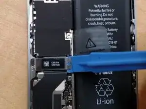
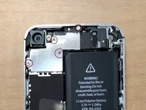
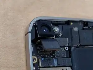
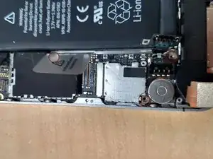
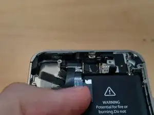
Use the head of your tool to take off the camera connector to the logic board
-
The camera is now safe to remove, put it in a safe place
-
-
-
Pry up the small grounding clip with the head of your tool and then remove it and put it in a safe place
-


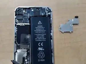


To reassemble your device, follow these instructions in reverse order.