Introduction
No audio? Replace the headphone jack!
-
-
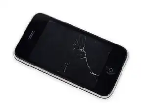
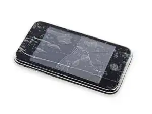
If your display glass is cracked, keep further breakage contained and prevent bodily harm during your repair by taping the glass.
-
Lay overlapping strips of clear packing tape over the iPhone's display until the whole face is covered.
-
-
-
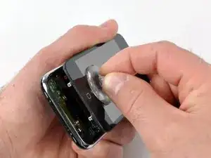
Remove the metal handle from the suction cup. It's easier and safer to grip the suction cup's base instead of the metal handle.
-
Use a small suction cup near the Home button to gently pull up the bottom portion of the iPhone's display assembly.
-
-
-
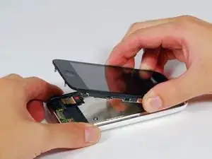
Continue to hold the display assembly with one hand, and use your other hand and a spudger to disconnect the black ribbon cable labeled "1". (Cable 1 is for the display)
-
-
-
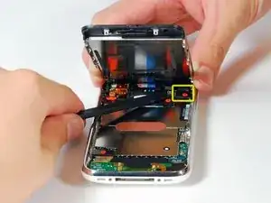
Rotate the display assembly up until it is roughly vertical. This will allow easier access for disconnecting the remaining cables.
-
Use a spudger to disconnect the black ribbon cable labeled "2". (Cable 2 is for the capacitative touch panel)
-
-
-
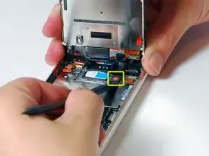
Use a spudger to flip up the white plastic tab holding the ribbon cable "3" in place. The white tab will rotate up 90 degrees, releasing the ribbon cable.
-
Slide the black ribbon cable out of its connector, and remove the display assembly from the iPhone.
-
-
-
Insert your SIM eject tool or a paper clip into the hole next to the headphone jack.
-
Press down on the tool until the SIM card tray pops out.
-
Grasp the SIM card tray and slide it out of the iPhone.
-
-
-
Remove the following 8 screws:
-
Five 2.3 mm Phillips #00 screws with partial threads securing the logic board to the rear case.
-
Two 2.3 mm Phillips #00 screws with full threads securing the logic board and camera.
-
One 2.9 mm Phillips #00 screw from beneath the "Do not remove" sticker.
-
Note for re-assembly:
-
The screw that goes next to the camera (bottom right orange highlighted screw) also has a metal strip that holds the camera in place.
-
-
-
Slide the logic board towards the dock connector and out of the iPhone.
-
When replacing the logic board after installing battery, connect the camera to the logic board before inserting it into the case. Then make sure to set the top section of the logic board (where the SIM tray is) in place before settling the rest of the board in place. This is important, as sometimes the SIM card slot will not align into place. Once the top section is in place, the bottom section can be maneuvered into place. You will know the logic board is correctly installed when the SIM tray is aligned with the opening in the iPhone case and the camera module seats neatly into its place.
-
-
-
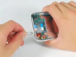
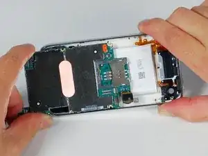
Use a spudger to pry the battery up from the rear case. The battery is attached with an adhesive strip around the perimeter of the battery.
-
-
-
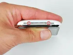
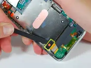
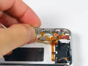
Remove the following 4 screws:
-
Three 1.8 mm Phillips #00 screws securing the headphone jack and GPS antenna to the rear case. Note the order in which you remove the screws, as the left one has a slightly larger head.
-
One 3.8 mm Phillips #00 screw in the plastic loop near the headphone jack.
-
-
-
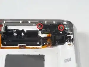
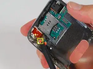
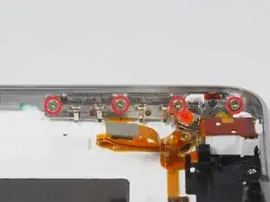
Remove the four Phillips #00 screws securing the volume and mute switch.
-
The mute switch assembly screws should be tightened with the switch in the off position. Check the protrusion of the switch when turned on, since it may not stick out far enough to operate if the switch assembly is incorrectly positioned. (Check the gap between the switch frame and the bezel (white gap showing between the two screws near the 6). The screw on the far right is slightly longer than the other 3 screws. When reassembling the phone, keep this in mind.
-
-
-
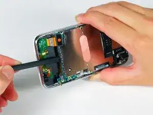
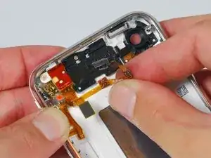
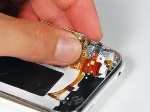
Carefully lift the headphone jack assembly out of the iPhone.
-
Switch the green mute switch down (towards the back side of the iPhone) into mute position. This will make it much easier to insert it, once the new mute button is in place.
-


To reassemble your device, follow these instructions in reverse order.

10 comments
I managed this in about an hour to fix a broken "volume up button" and combined with replacing a broken ringer/mute switch. Thanks for the guide!!!
Two very minor comments to consider:
- Step 19 indicates three 1.8mm screws and one 3.8mm. In my 3G i found the middle "1.8mm screw" is actually smaller. Hopefully this helps someone who didn't notice that on the way out...
- Step 14 doesnt mention the flexible clip that is attached to the logic board and fits under the bezel on the right hand side near the dock connector end. Most people will find it anyway, but it might help those like me (who are pushing the limits of their technical skills) to note the preferred method for handling this. I just moved the logic board towards the opposite side and popped it out with a screw driver...
These are only minor points but overall i found the guide to be excellent and much easier to follow than anything else i found including you tube videos etc.
Paul -
Quote from Paul:
I managed this in about an hour to fix a broken "volume up button" and combined with replacing a broken ringer/mute switch. Thanks for the guide!!!
Two very minor comments to consider:
- Step 19 indicates three 1.8mm screws and one 3.8mm. In my 3G i found the middle "1.8mm screw" is actually smaller. Hopefully this helps someone who didn't notice that on the way out...
- Step 14 doesnt mention the flexible clip that is attached to the logic board and fits under the bezel on the right hand side near the dock connector end. Most people will find it anyway, but it might help those like me (who are pushing the limits of their technical skills) to note the preferred method for handling this. I just moved the logic board towards the opposite side and popped it out with a screw driver...
These are only minor points but overall i found the guide to be excellent and much easier to follow than anything else i found including you tube videos etc.
i broke the little tab in the bottom of the main board, now my network service is always low, its connected to the signal right? is it okay to solder a piece of wire there so that it can touch the metal bezel?
Nap -
I replaced this part successfully but my phone still thinks it's in headphone mode. There is obviously no lint in a new jack so plugging/unplugging a set of headphones isn't working. What else would cause my phone to only have sound with headphones plugged in?
pgatj -