Introduction
A 20 (?) year old Yamaha rxe100 amplifier with built-in tuner had an intermittent problem with both speakers turning off erratically. This gradually got worse with age, til it was only useable on the headphones. When the speakers turned on or off I could hear a click, which was the speaker relay closing or opening. (Not to be confused with quieter sound of the power relay which turns on almost instantaneously when the standby/on button is pressed)
The fault was believed to be due to failure of the speaker protection circuitry. The work-around was to solder two wires across the speaker relay pins then checking that the dc offset at the speaker terminals was satisfactory (eg less than 50mV). If greater than about 600mV the speaker protection circuitry was doing its job and was not the fault and the soldered-in wires should be removed and different repair sought.
-
-
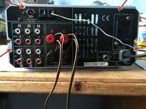
Remove 4 screws from the back (shown) and 4 from the side and slide the top cover back and up the remove.
-
More disassembly detail is shown in page 6 of the widely available rxe100 service manual online (free)
-
-
-
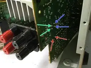
Check that the idling current between the arrowed test points (of the same colour) is 0.1-15mV at start-up or 0.25-15mV after 1 hour for both resistors. Mine was a satisfactory 0.9mV.
-
Further details can be found on page 8 in the 'RXE100 service manual' widely available for free on-line.
-
-
-
The speaker relay is the black box, marked DEC DH2TU 24V 3A, near the speaker connections. It's not necessary, but if you want to see this relay, you need to remove the top and side PCB by removing 2 screws joining the side PCB to the main PCB.
-
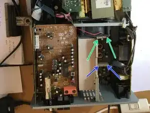
To get access to the relay's soldered pins, you need to lift up the largest printed circuit board (PCB). This is done by removing 5 copper coloured screws from this PCB (note: one is hidden under the fan assembly).
-
Further disassembly details can be found in the online RXE100 service manual page 6. Check that the relay's coil voltage between green arrows is zero volts in the non-working condition ( 24V when working properly), check you have not left the headphone jack in.
-
If you have 0V between the red arrows, this explains why you have no sound from the both speakers. The work-around here, at your own risk, is to solder a wire between the green pins and another wire between the blue pins.
-
Both speakers should now work. You may notice a slight thump from the speakers when turning on and the speakers will not mute when you plug in headphones. But these are minor problems. ps Perhaps don't do this repair if using your prized speakers as they will have less protection against future amplifier faults.
-
Now the speakers are working you can check the dc bias across each of the speaker terminals and subwoofer. Mine were satisfactory at <10mV dropping to 0.5mV after a few minutes
-
Internet guidance suggest dc bias below 50mV is acceptable. Above this you may get distortion. If above about 600mV may cause damage and would be why the protection circuitry is operating, in which case remove the soldered-in wires and find a repair for a dc offset fault.
-
To reassemble your device, follow these instructions in reverse order. Make a note on the amplifier that the speaker relay has been bypassed (to help with any future repair)