Introduction
Use this guide to replace the motherboard in an Xbox Series X.
You can also use this guide to reapply thermal paste in your Xbox.
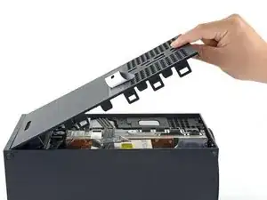
Before you begin, completely power down and unplug all cables from your console. Remember to follow general electrostatic discharge (ESD) safety procedures while repairing the console.
-
-
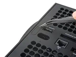
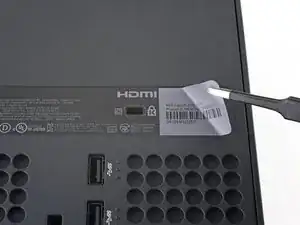
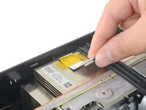
Use a pair of tweezers to remove the sticker hiding the first screw on the back panel, near the base.
-
-
-
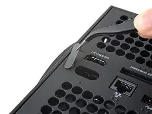
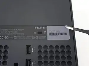
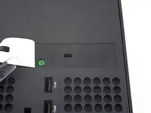
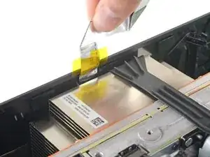
Use a pair of blunt tweezers to peel back the large sticker on the back panel to reveal the second screw.
-
-
-
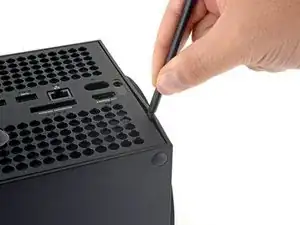
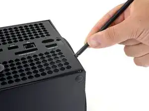
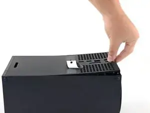
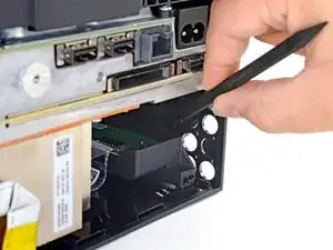
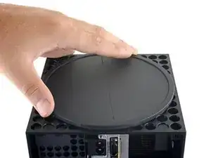
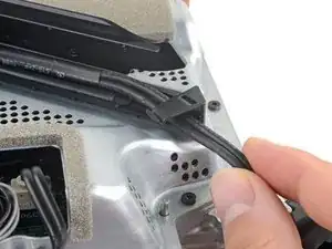
Insert the flat end of a spudger into the gap between the back panel and the shell, near the left side of the base.
-
Pry up the back panel to release it from the locking clips.
-
-
-
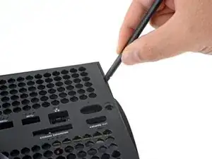
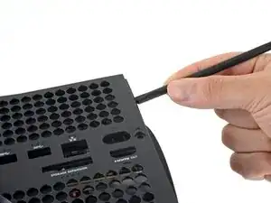
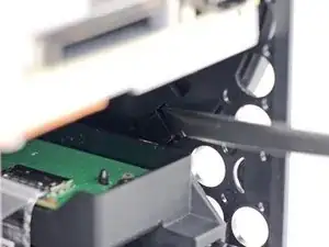
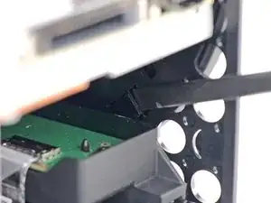
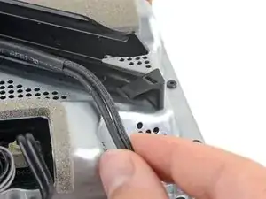
Insert the flat end of a spudger into the gap between the back panel and the shell, near the right side of the base.
-
Pry up the back panel to release it from the locking clips.
-
-
-
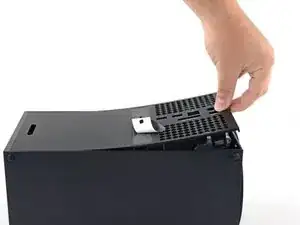
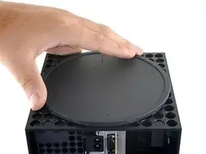
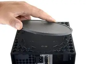
Grip the back panel at the opening you just created and pull it up and away from the shell to unclip the long edges.
-
-
-
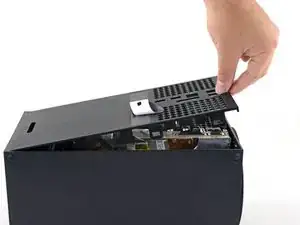
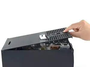
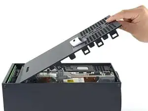
Tilt the back panel up and pull it away from the top edge of the shell to release it from the gap.
-
Remove the back panel.
-
-
-
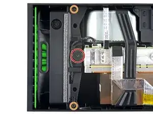
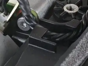
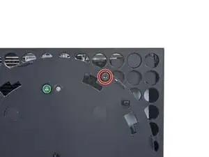
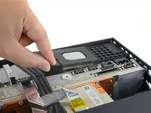
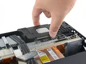
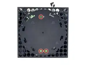
Use a T8 Torx driver to remove the three screws securing the fan to the center chassis:
-
One 10.5 mm pancake screw
-
Two 8.8 mm screws
-
-
-
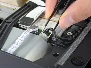
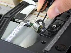
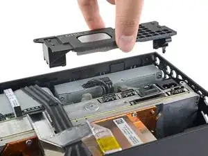
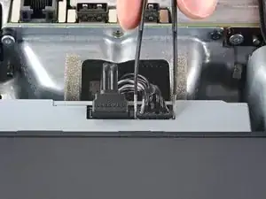
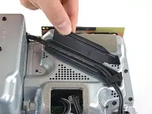
Use your fingers or a pair of blunt tweezers to grip the edges of the fan cable connector, and pull up to disconnect it from the center chassis.
-
-
-
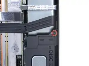
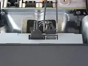
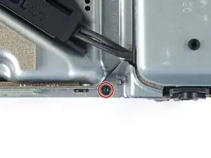
Use a T8 Torx driver to remove the two 8.8 mm screws securing the optical drive's vibration isolator to the shell: one on the base and one on the top of the isolator.
-
-
-
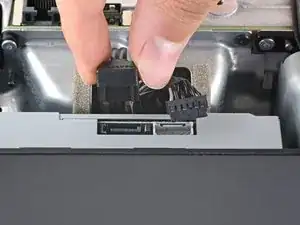
Use a pair of blunt tweezers to grip the edges of the optical drive power connector and pull up to disconnect it from the optical drive.
-
Use your fingers to pull up and disconnect the data cable from the optical drive.
-
-
-
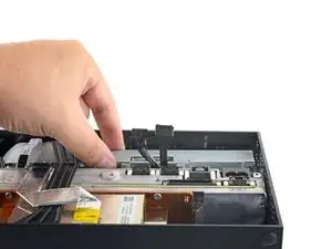
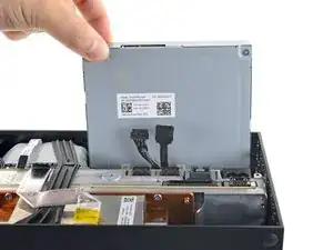
Grip the top edge of the optical drive and pull it out of its slot in the shell to remove it.
-
-
-
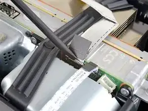
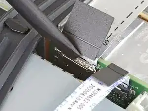
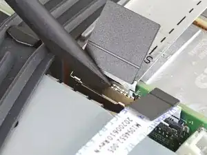
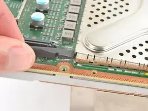
Use the flat end of a spudger to flip open the metal locking tab on the USB port ribbon cable.
-
-
-
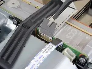
Use a pair of tweezers to pull up on the black plastic pull tab to disconnect the USB port cable.
-
-
-
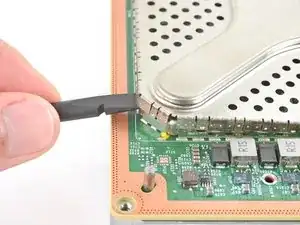
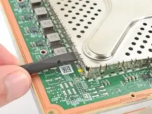
Use the pointed end of a spudger to depress the metal tab on the side of the power button cable's board connector.
-
With the metal tab depressed, use a pair of tweezers to pull up on the pull tab to disconnect the power button cable from the center chassis.
-
-
-
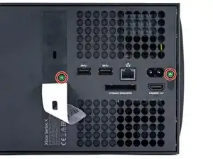
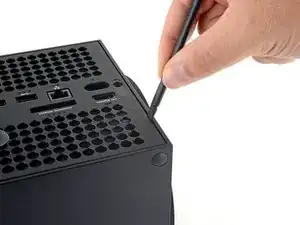
Use a T8 Torx driver to remove the three 7.4 mm screws securing the center chassis assembly to the shell.
-
-
-
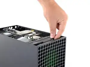
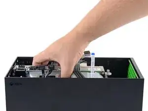
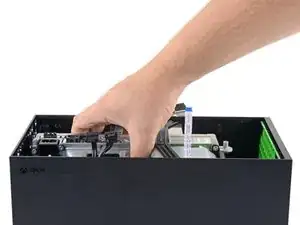
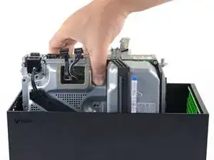
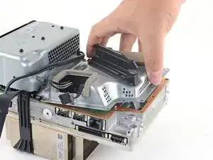
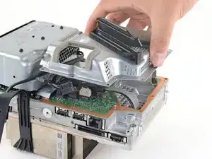
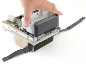
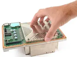
Grip the center chassis and pull it towards the green fan grille at the top of the shell, uncoupling the guide pegs from the shell.
-
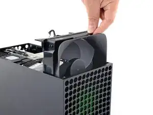
Lift out the center chassis assembly to remove it from the shell.
-
-
-
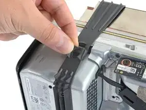
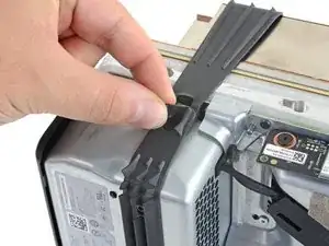
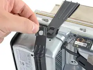
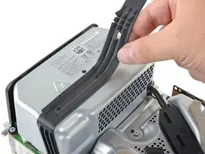
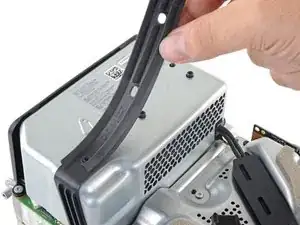
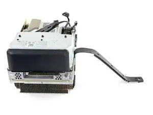
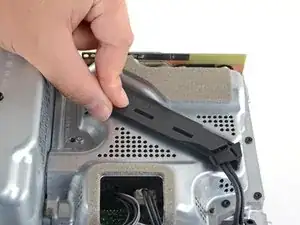
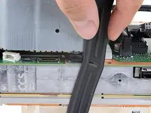
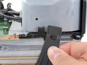
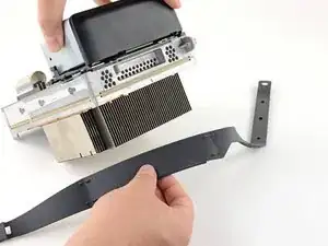
Pull the chassis strap over and off of the power supply.
-
Once the strap is off of the power supply, set the loose section to the side.
-
-
-
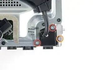
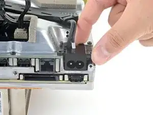
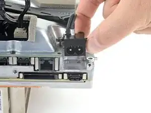
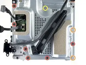
Use a T8 Torx driver to remove the three screws securing the power cable port to the chassis:
-
Two 13.1 mm screws
-
One 35 mm screw
-
-
-
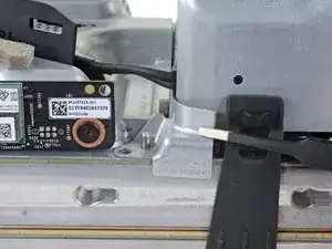
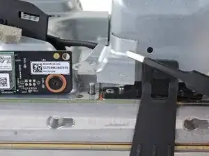
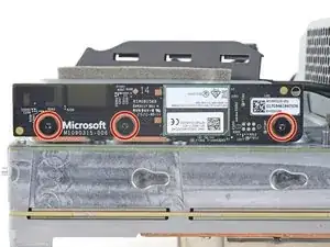
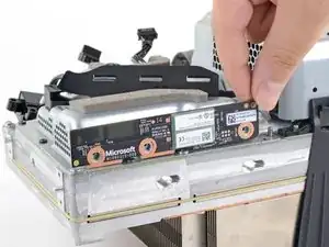
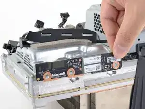
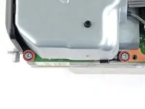
Use a T8 Torx driver to remove the three 9.6 mm screws securing the accessory antenna board to the center chassis.
-
-
-
Use a T8 Torx driver to remove the nine screws securing the board shield:
-
Six 8.8 mm black screws
-
Two 35 mm silver screws
-
One 13.1 mm silver screw
-
-
-
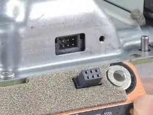
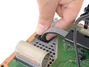
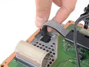
Grip and compress the locking tab on the 10-pin power connector.
-
While compressing the locking tab, lift the connector straight up to disconnect it from the board.
-
-
-
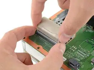
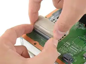
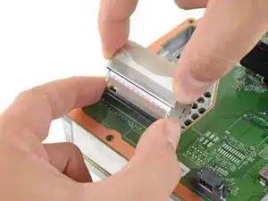
Grip the base of the interconnect cable connector with your fingers.
-
Depress each side of the connector to unlock the cable locking tabs.
-
With the locking tabs depressed, grip the edges of the interconnect cable and pull it straight out of the connector to disconnect it.
-
-
-
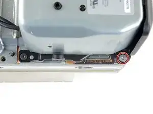
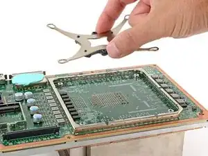
Use a T8 Torx driver to remove the three 35 mm‑long silver screws from the power supply—leave the fourth black screw in place.
-
-
-
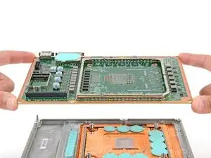
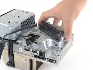
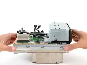
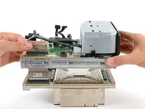
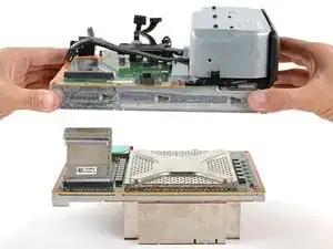
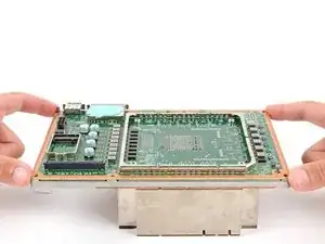
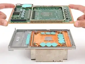
Grip the edges of the center chassis (not the power supply) and lift it off of the motherboard and heatsink assembly, routing the interconnect cable through its cutout.
-
-
-
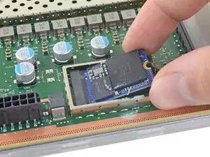
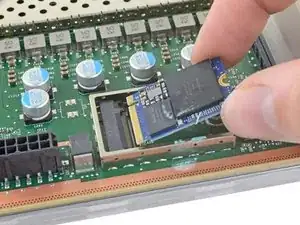
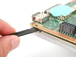
Use the flat end of a spudger to pry up the edges of the metal SSD shield.
-
Remove the SSD shield.
-
-
-
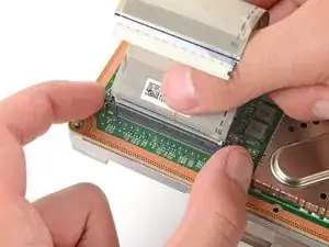
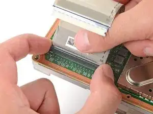
Grip the base of the interconnect cable connector with your fingers.
-
Depress each side of the connector to unlock the cable locking tabs.
-
With the locking tabs depressed, grip the edges of the interconnect cable and pull it straight out of the connector to disconnect it.
-
Remove the interconnect cable.
-
-
-
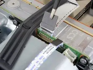
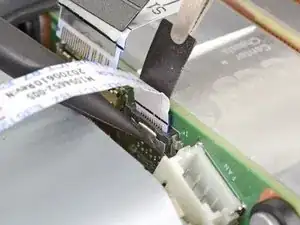
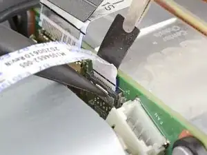
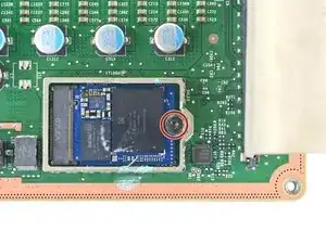
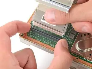
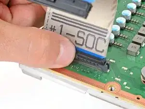
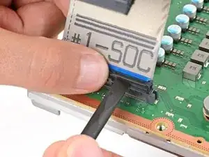
Pinch the locking tab on the interconnect cable on the motherboard and use the flat end of a spudger to disengage the clip.
-
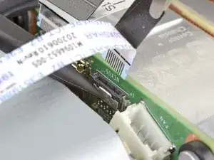
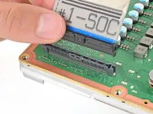
Use your fingers to pull the connector straight up and out of its socket.
-
-
-
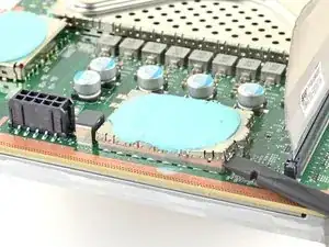
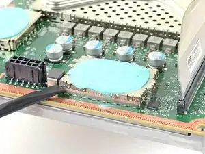
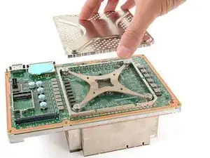
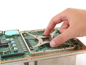
Use the flat end of a spudger to pry up the edges of the large metal shield in the center of the motherboard.
-
-
-
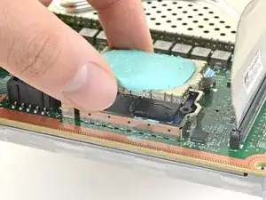
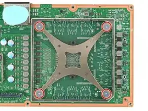
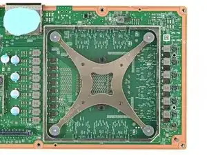
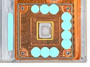
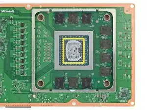
Check the condition of the thermal putty—it'll be on the heatsink and/or the motherboard.
-
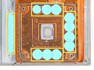
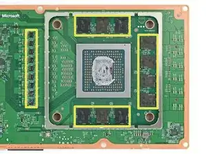
If any pieces are damaged or dried out, remove and replace them:
-
Use a spudger to gently scrape up larger pieces of putty, being very careful not to damage anything on the board.
-
Use isopropyl alcohol and coffee filters or cotton swabs to clean up all the thermal putty residue.
-
Apply new pieces of putty (not thermal paste) that are the same size and shape as the originals.
-


To reassemble your device, follow these instructions in reverse order.
Take your e-waste to an R2 or e-Stewards certified recycler.
Repair didn’t go as planned? Try some basic troubleshooting, or ask our Xbox Series X Answers community for help.

3 comments
There are five completely unnecessary steps in this guide all centered around removing the PSU and the part under it that don't need to be done in order to remove the motherboard/heatsink. You can cut out steps 38, 39, 41, 42 and 43 on step 40 you only need to remove the three 35mm screws to complete the step. As long as you complete the rest of the guide the top comes away without issue.
Thanks....... I just had one apart and skipped those steps with no problems.
If you replace the motherboard will the disk drive still work?