Introduction
Use this guide to replace a faulty optical drive in an Xbox Series X (2TB Galaxy Black edition).
Before you begin, completely power down and unplug all cables from your console. Remember to follow general electrostatic discharge (ESD) safety procedures while repairing the console.
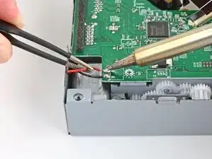
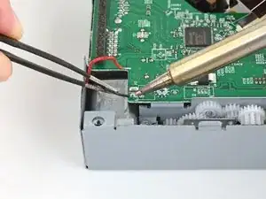
The board inside the optical drive is software-linked to the console’s motherboard. This board will need to be transferred into the replacement optical drive to restore full functionality. This will require you to de-solder and solder two wires. Follow general soldering safety guidelines such as wearing eye protection, working in a well-ventilated area, and washing your hands after with soap and water after soldering.
-
-
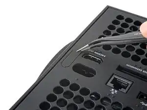
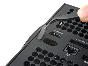
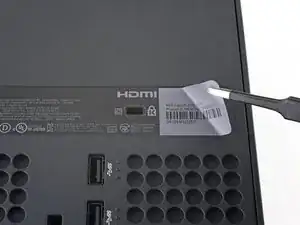
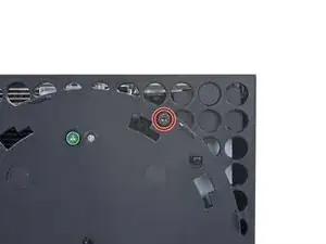
Use a pair of tweezers to remove the sticker hiding the first screw on the back panel, near the base.
-
-
-
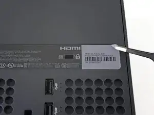
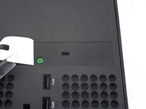
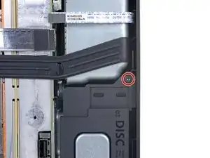
Use a pair of blunt tweezers to peel back the large sticker on the back panel to reveal the second screw.
-
-
-
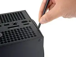
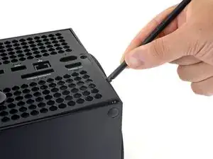
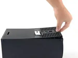
Insert the flat end of a spudger into the gap between the back panel and the shell, near the left side of the base.
-
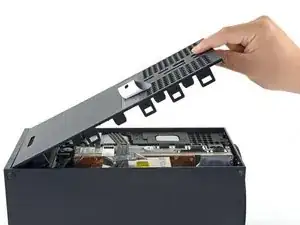
Pry up the back panel to release it from the locking clips.
-
-
-
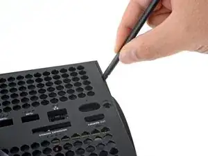
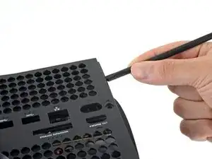
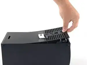
Insert the flat end of a spudger into the gap between the back panel and the shell, near the right side of the base.
-
Pry up the back panel to release it from the locking clips.
-
-
-
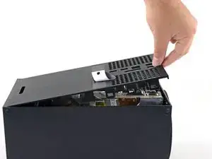
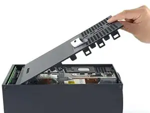
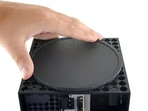
Grip the back panel at the opening you just created and pull it up and away from the shell to unclip the long edges.
-
-
-
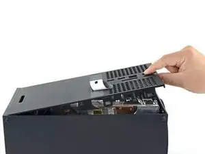
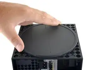
Tilt the back panel up and pull it away from the top edge of the shell to release it from the gap.
-
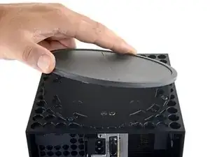
Remove the back panel.
-
-
-
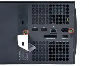
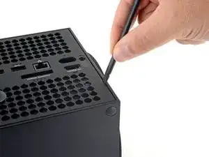
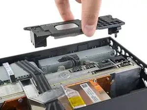
Use a T8 Torx driver to remove the two 8.8 mm screws securing the optical drive's vibration isolator to the shell: one on the base and one on the top of the isolator.
-
-
-
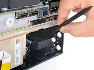
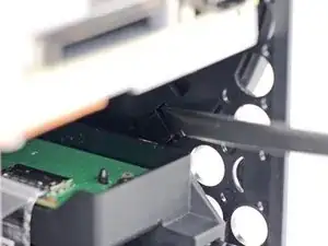
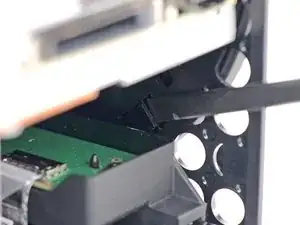
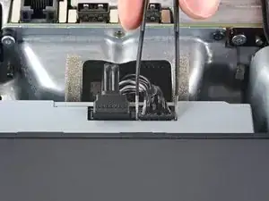
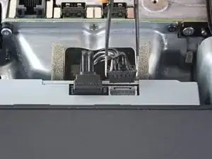
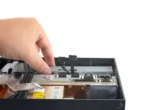
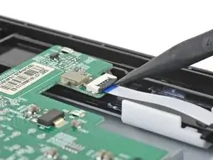
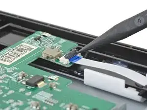
Use a pair of blunt tweezers to grip the edges of the optical drive power connector and pull up to disconnect it from the optical drive.
-
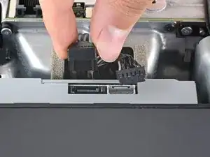
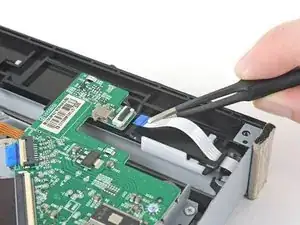
Use your fingers to pull up and disconnect the data cable from the optical drive.
-
-
-
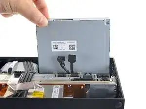
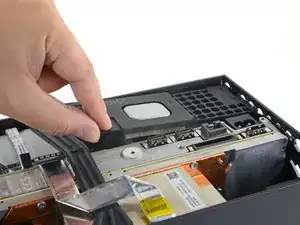
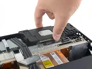
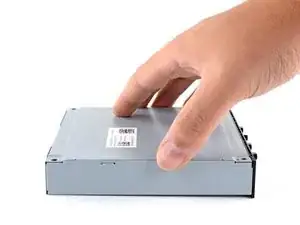
Grip the top edge of the optical drive and pull it out of its slot in the shell to remove it.
-
-
-
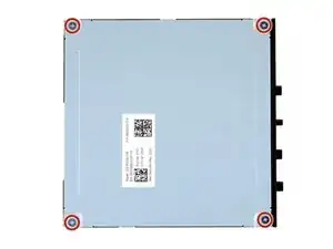
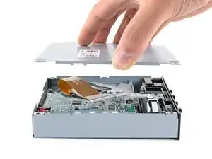
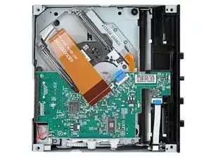
Use a Phillips screwdriver to remove the four 3.6 mm screws securing the optical drive cover.
-
-
-
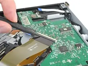
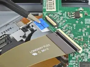
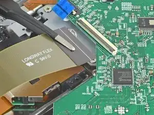
Use the pointed end of a spudger to flip up the hinged locking tab on the large ribbon cable's ZIF connector.
-
-
-
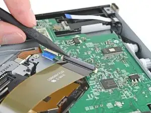
Use the pointed end of a spudger to flip up the hinged locking tab on the small ribbon cable's ZIF connector.
-
-
-
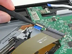
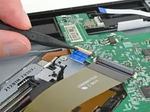
Use the pointed end of a spudger to flip up the hinged locking tab on the small ribbon cable's ZIF connector, near the corner of the optical drive.
-
-
-
Use a pair of blunt tweezers to remove each of the three ribbon cables from their connectors.
-
-
-
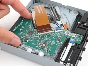
Use a Phillips screwdriver to remove the three 3.3 mm‑long screws securing the optical drive board.
-
-
-
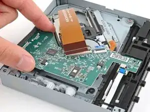
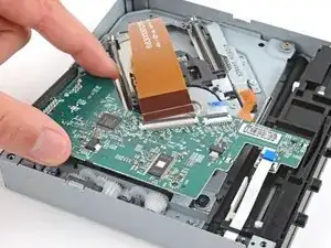
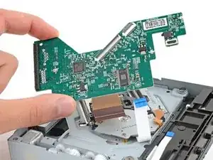
Lift the edge of the board near the plastic gears and slide the board towards the edge so it comes out from under the clip near the barcode.
-


To reassemble your device, follow these instructions in reverse order.
Take your e-waste to an R2 or e-Stewards certified recycler.
Repair didn’t go as planned? Try some basic troubleshooting, or ask our Xbox Series X Answers community for help.
