Introduction

Use this guide to replace the Wi‑Fi antenna board in your Xbox Series X (Digital Edition) gaming console.

Before you begin, completely power down and unplug all cables from your console. Remember to follow general electrostatic discharge (ESD) safety procedures while repairing your console.

  1. AypelPgoTxaJoKFD
    AypelPgoTxaJoKFD
    KBWiDZuUDl4RA3uo
    • Before you begin, completely power down and unplug all cables from your console.

    • Two stickers cover the back panel screws. You can remove the stickers without heating them, though it makes them much easier to remove cleanly.

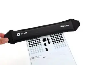
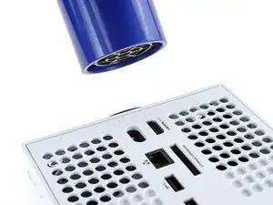
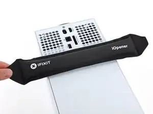
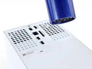
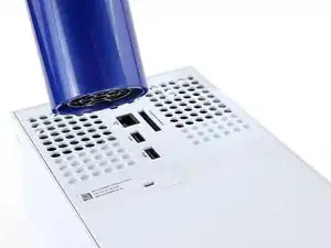
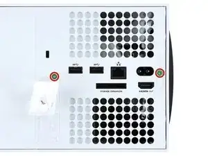
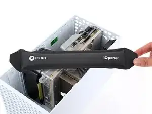
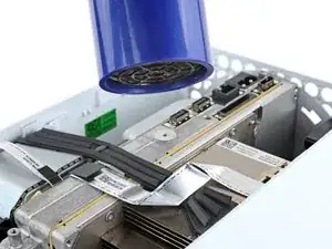
    • Heat an iOpener and lay it on the smaller sticker near the bottom of the back panel for two minutes.

    • Alternatively, you can use a hair dryer to heat the sticker.

  2. v1dUpQQS2lYRLUsH
    v1dUpQQS2lYRLUsH
    NdNRckQLBpYFQ61D
    31oUFi4UvURQcjXq
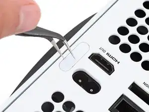
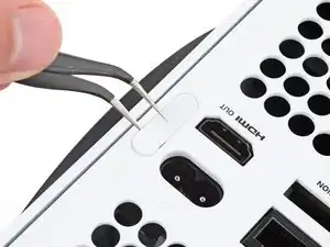
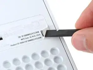
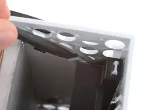
    • Use a pair of angled tweezers to remove the sticker hiding the first screw on the back panel, near the base.

  3. nemuGwbC1YIXKi66
    nemuGwbC1YIXKi66
    O1eLVGlYtZKcUcXP
    CybW5HMbXROJs2KC
    • Use an iOpener or hair dryer to heat the larger sticker near the center of the back panel.

  4. AcTPiFLqqo4HCDDk
    AcTPiFLqqo4HCDDk
    MWiWBWw3sVFtUcAl
    L2Wo6IJA3FaCf24P
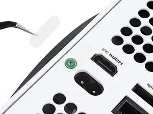
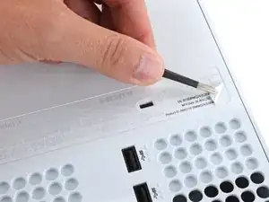
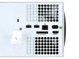
    • Use the flat end of a spudger to scrape up a corner of the larger sticker until you can grip it with a pair of blunt tweezers.

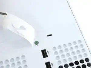
    • Use blunt tweezers to peel back the sticker to reveal the second screw.

    • You only need to peel this sticker to where you can access the hidden screw. You don't need to pull it completely off.

    • Technically, these are tamper-evident stickers, but don't worry—Microsoft can't legally void your warranty, as long as you don't damage anything. Have fun!

  5. sfZXSBU5uaVytGCV
    sfZXSBU5uaVytGCV
    GYYYlm1IAdKDHBJw
    • Throughout this repair, keep track of each screw and make sure it goes back exactly where it came from to avoid damaging your console.

    • Use a T8 Torx driver to remove the two 7.4 mm‑long screws securing the back panel.

  6. FDxR4GKjpo2HjiLo
    FDxR4GKjpo2HjiLo
    xuBkTmX4myZlb2fR
    jYXiT5eNXiDEHkqO
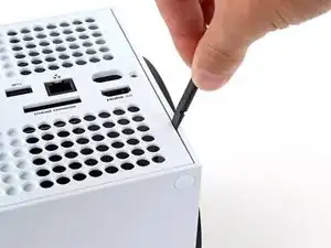
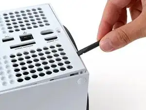
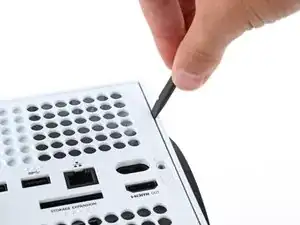
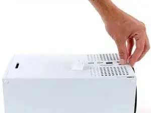
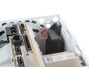
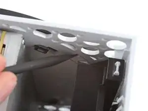
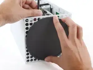
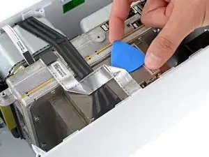
    • Insert the flat end of a spudger into the gap between the back panel and the shell, near the left side of the base.

    • Pry up the back panel to release it from the locking clips.

  7. NLuvivjpUaQttKDs
    NLuvivjpUaQttKDs
    glqOhiOkIMunabBR
    xSlNfvUnBDAYtVuy
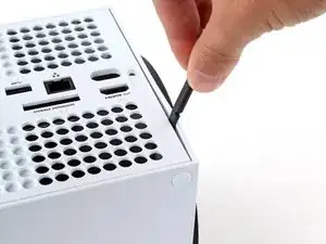
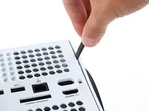
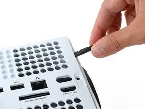
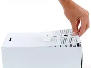
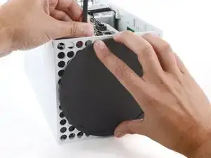
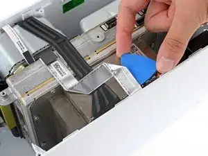
    • Insert the flat end of a spudger into the gap between the back panel and the shell, near the right side of the base.

    • Pry up the back panel to release it from the locking clips.

  8. raEhJf4j2JANGjUA
    raEhJf4j2JANGjUA
    32vpOrKlSKiiVUtI
    rJTbeew1aHSNj3Xv
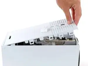
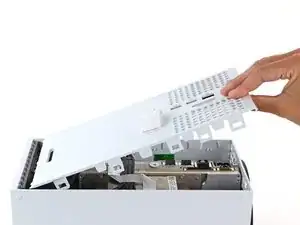
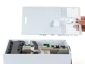
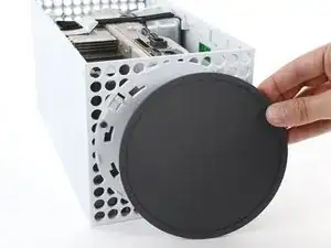
    • Grip the back panel at the opening you just created and pull it up and away from the shell to unclip the long edges.

    • During reassembly, press along the edges of the back panel to snap it into place.

  9. xGEgfdsnC5tVhFJR
    xGEgfdsnC5tVhFJR
    rjEGrstSYJdOd4Jo
    fXODEtKZ1v4wrFv5
    • The back panel slots into a gap at the top of the shell.

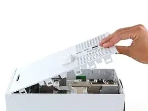
    • Tilt the back panel up and pull it away from the top edge of the shell to release it from the gap.

    • Remove the back panel.

  10. MPn4ah3bCZ1yWKh6
    MPn4ah3bCZ1yWKh6
    6sgE3f5LenMyJxPP
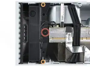
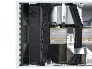
    • Use a T8 Torx driver to remove the three screws securing the fan to the center chassis:

    • One 10.3 mm‑long pancake screw

    • Two 9 mm‑long screws

  11. 6PffkpqSeHgZbNP2
    6PffkpqSeHgZbNP2
    SGxpn2kGptsFojbq
    vgIxTrICJRbnfqr2
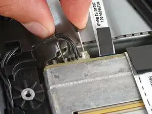
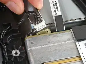
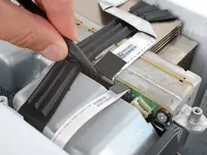
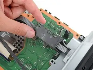
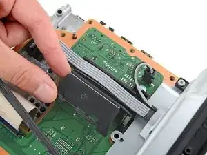
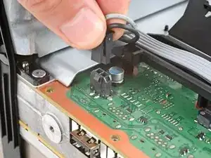
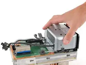
    • Use your fingernails or a pair of angled tweezers to firmly grip the edges of the fan cable connector.

    • Grip your tweezers close the connector to get a better grip.

    • Pull the connector straight out of the socket to disconnect it.

    • If you're having trouble, gently rock the connector side to side to loosen it.

    • Always pull cables by their connectors and not the wires themselves.

    • During reassembly, route the fan cable underneath its small cable guide on the fan housing so it doesn't interfere with the back panel.

  12. XQyZlR4cxMHjoGYx
    XQyZlR4cxMHjoGYx
    4Ko4B5a52LGmHPTU
    5YKemIevYGVQlJPT
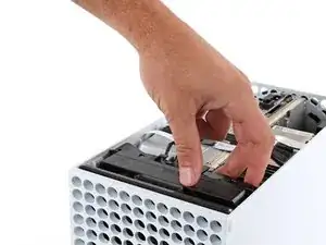
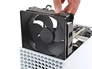
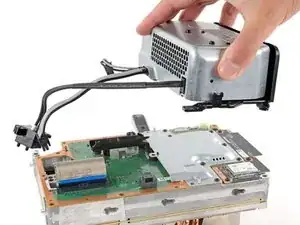
    • Slide the fan out of its slot to remove it.

    • During reassembly:

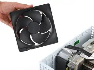
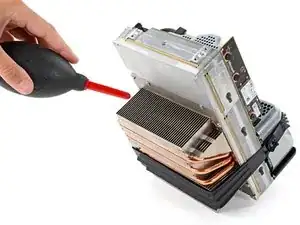
    • Before installing the fan, make sure it's clean! Use a dust blower or compressed air to blow off any dust or debris, and wipe the fan clean with a clean cloth.

    • Use a finger to keep the fan blades steady—it makes them easier to clean.

    • Note that the fan can only be installed one way—make sure Master Chief is facing you.

  13. q2IjeBcCiqngZVmC
    q2IjeBcCiqngZVmC
    PSNU41LBk2EQFy6h
    KaX1PCOwa4vmE5V3
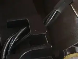
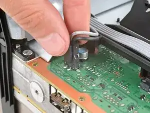
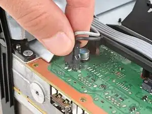
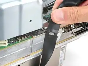
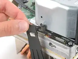
    • Use the flat end of a spudger to pry up the locking tab holding the base to the shell.

    • Keep the locking tab held open for the next step.

  14. rJtyV5W2NHU2B1JM
    rJtyV5W2NHU2B1JM
    66KXLCGWJ6CxJ2op
    aPdFxgVqAKbHN4cM
    • With the locking tab held open, grip the base and rotate it counterclockwise to unlock it from the shell.

    • Remove the base.

    • During reassembly, put the base tabs into their holes on the shell and twist clockwise until the base snaps into the interior locking tab.

    • When locked in place, the Hello from Seattle line will be parallel with the device's sides.

  15. NeKUM2qvcQQVBHJJ
    NeKUM2qvcQQVBHJJ
    P2LeNqUV6RRYpXcU
    M6GqHbshyaRYaEDj
    • The ribbon cables and their connectors are extremely fragile, so always open locking tabs gently and pull cables slowly.

    • Use a spudger to flip open the metal locking tab on the USB port ribbon cable.

    • During reassembly, gently snap the metal locking tab back into place once the cable has been inserted.

  16. GOmZT2eVDdlKkB2I
    GOmZT2eVDdlKkB2I
    6PHosomvtSYWSayL
    yOPyxPLEC4vpHgFD
    • The USB port cable is secured to the chassis with two pieces of mild adhesive.

    • Use an iOpener or a hair dryer to heat the USB port cable.

  17. ZCkD63XIwjldOj1v
    ZCkD63XIwjldOj1v
    NpeCgrhqBrrZpFB1
    WcH6vDHlhMxk2Cnl
    • Slide an opening pick under the USB port cable to separate the adhesive securing it.

    • During reassembly, use thin double‑sided adhesive to secure the cable. If there's adhesive left and it's still sticky, you can reuse it. If you have a new cable, check it for pre‑installed adhesive and remove any liners.

  18. IUrTYmFqEgufqVOU
    IUrTYmFqEgufqVOU
    LvAP1UVRBLQEcJda
    cuKWg24u2HTDBfB2
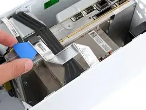
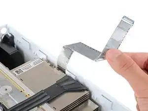
    • Use a pair of tweezers to gently pull up on the black plastic pull tab to disconnect the USB port cable.

    • Pull only on the pull tab, not the cable itself.

    • Move the USB port cable out of the way of the chassis.

  19. DMIaBGOtoPPGNGHD
    DMIaBGOtoPPGNGHD
    HoOQqRfBAieYJN2R
    SnsY64eWouKrZuXQ
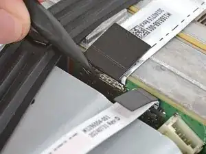
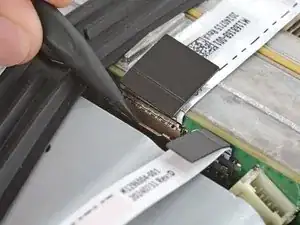
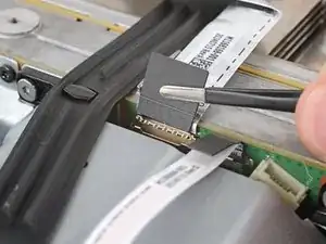
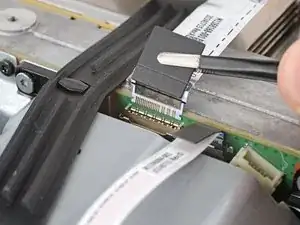
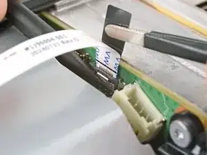
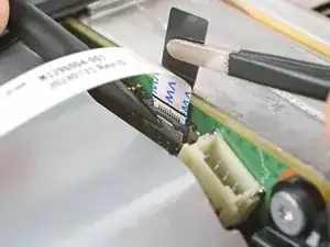
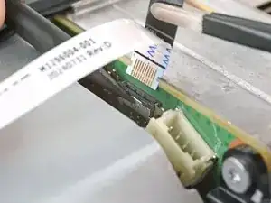
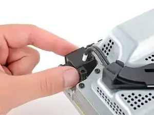
    • Use the pointed end of a spudger to depress the metal tab on the side of the power button cable's board connector.

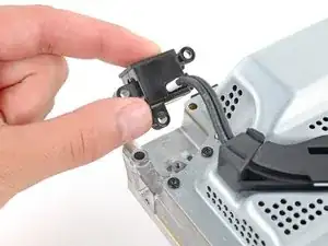
    • With the metal tab depressed, use a pair of tweezers to pull up on the pull tab to disconnect the power button cable from the center chassis.

    • Pull only on the pull tab, not the cable itself.

    • Don't pull on the cable without depressing the metal tab, otherwise you risk damaging either the cable or the connector.

    • During reassembly, the cable should lightly "snap" into place when inserted.

  20. FeRCKSUSYmcDEaca
    FeRCKSUSYmcDEaca
    VMBvSXHZmiBbxVuC
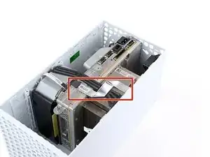
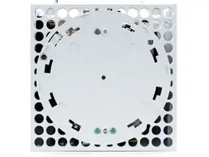
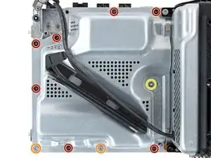
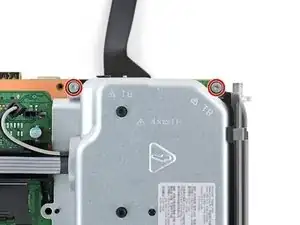
    • Use a T8 Torx driver to remove the three 7.4 mm‑long green screws securing the center chassis assembly to the shell.

  21. G5fXpkuI4BGkkQOR
    G5fXpkuI4BGkkQOR
    dENPOhBCp1VNtDD3
    QANxVvcldCkucVOZ
    • The center chassis assembly is aligned to the bottom of the shell with guide pegs. These pegs will need to slide out of their slots to allow the chassis to be lifted out.

    • Grip the chassis and pull it towards the top of the shell, uncoupling the guide pegs from the shell.

    • Use two hands to lift out the chassis to remove it from the shell.

    • During reassembly:

    • Make sure neither of the ribbon cables get pinched as you lower the center chassis into the shell.

    • Use the alignment pegs and cutouts to properly orient the chassis in the shell:

    • Two pegs on the chassis with cutouts on the bottom of the shell.

    • Three pegs in the shell with cutouts on the chassis.

  22. dkJWbTlLhb2VtF24
    dkJWbTlLhb2VtF24
    YhJWxpLjQb3ICtBE
    • Gently place the chassis heatsink-side down on a clean work surface.

    • During reassembly, this is a good point to clean the heatsink fins of any dust, dirt, or debris that may have built up over time. Use a dust blower or compressed air to clear out the fins.

  23. bCZlVYbCeYWLNPO2
    bCZlVYbCeYWLNPO2
    kfqk4xAQRFf3WC4j
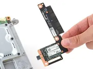
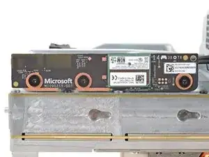
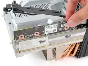
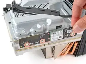
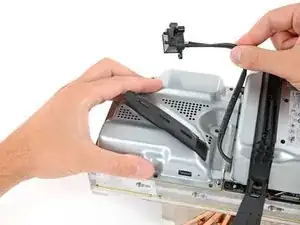
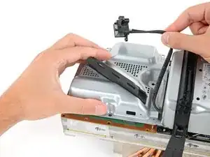
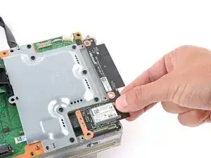
    • Use a T8 Torx driver to remove the three 9.6 mm‑long screws securing the antenna board to the center chassis.

  24. TbTnEVunHMgXVtjx
    TbTnEVunHMgXVtjx
    aXOggJBCMXbrCNkG
    QjLFK6kKIELBRB2b
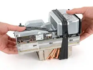
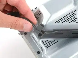
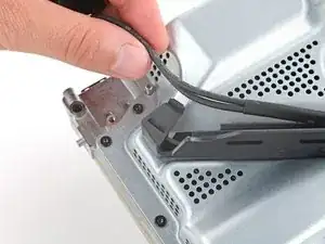
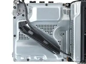
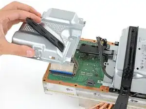
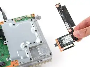
    • Grip the top right corner of the antenna board and pull it directly away from the center chassis to disconnect it.

    • During reassembly, align the board's connector with the port on the center chassis and press to reconnect.

  25. KrZfXIlegalLQXyn
    KrZfXIlegalLQXyn
    chkBWKxwllEUUWjo
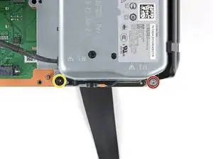
    • Use a T8 Torx driver to remove the three screws securing the power cable port to the chassis:

    • Two 13.1 mm‑long screws

    • One 35 mm‑long screw

  26. eRwtodYRaX5SFkfW
    eRwtodYRaX5SFkfW
    MFnfRXMWAHmWQsBZ
    • Lift the power connector out of its recess in the chassis.

  27. I2ADIyVhLoi2H1Ss
    I2ADIyVhLoi2H1Ss
    Ud2YtfstA3MWGiAI
    • Unlatch and open the lid on the power cable's plastic guide.

  28. s2jx6QE5UZVqCnu6
    s2jx6QE5UZVqCnu6
    y2jVnvSFTRZpPIoQ
    • Lift the power cable out from underneath the extra section of the cable guide.

  29. kdVNQWjXWQeNxtT6
    kdVNQWjXWQeNxtT6
    TJQAUdAyqmDvBbKX
    • Use a T8 Torx driver to remove the ten screws securing the board shield:

    • Seven 8.7 mm‑long screws

    • Two 35 mm‑long screws

    • These screws are very tight and may take significant force to loosen.

    • One 13 mm‑long screw

  30. yqHbnGMZjC6auQF3
    yqHbnGMZjC6auQF3
    qeGZEiixDEY2U1LJ
    QIBDSiDUcVF1BKwD
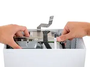
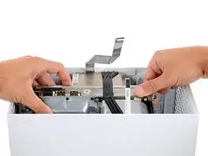
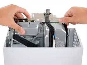
    • Hold the power supply cable out of the way and lift the board shield straight up to remove it.

  31. CKxZt4kXBkJVja12
    CKxZt4kXBkJVja12
    Sut11i5MCweZRkNG
    yE5XOIl2g3wJ646W
    • Open the lid on the power supply's plastic cable guide.

  32. GC1knsWOpf4FiRFc
    GC1knsWOpf4FiRFc
    yC2iGmxvd1RbYo2S
    CUcfygYFyCCIKjsv
    • Always pull cables by their connectors and not the wires themselves.

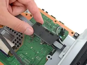
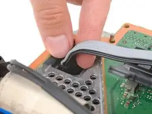
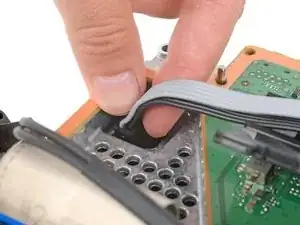
    • Use your fingers to pinch the power supply's two‑pin power connector, so the locking tab opens outward.

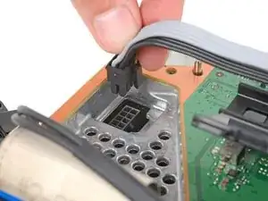
    • With the locking tab open, lift the connector straight up and out of its socket.

  33. eHQAVteodTBH4ULh
    eHQAVteodTBH4ULh
    iYrFuubURkHaCgKQ
    BAcwMqIZAEhSNmbe
    • Repeat the previous step to disconnect the power supply's 10‑pin connector.

  34. bwQbI4LJcIMWp5dh
    bwQbI4LJcIMWp5dh
    uASBpjekAyY3KNYu
    bIVfeGYVmYtSRCxG
    • Pull the end of the rubber strap down and away from the chassis to unlatch it.

  35. Uy3C6ldkpPFQ53XW
    Uy3C6ldkpPFQ53XW
    PFA23lflMpOhk1nL
    JCQft2vVc4BYROJn
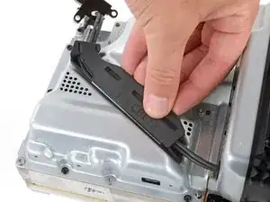
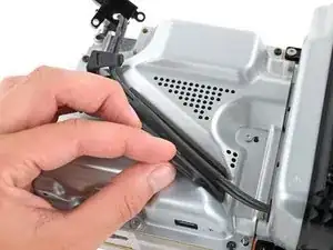
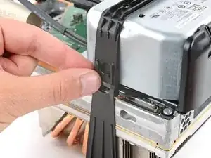
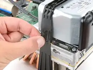
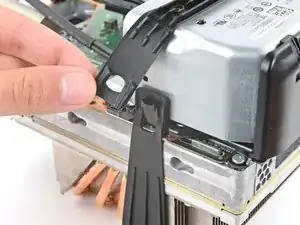
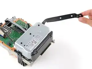
    • Pull the chassis strap off its three alignment posts and unlatch it from the sides of the power supply.

    • You can leave the strap under the chassis or remove it.

    • During reassembly, make sure the nubs in the middle of the strap go unto their cutouts on the heat sink fins.

  36. aIHnxLoR4jMfIY5C
    aIHnxLoR4jMfIY5C
    6FUVvTNQQdqY5vt3
    • Use a T8 Torx driver to remove the four screws securing the corners of the power supply:

    • Three 35 mm‑long silver screws

    • One 8.7 mm‑long black screw

  37. MqVOhdQvxBDEMIGq
    MqVOhdQvxBDEMIGq
    hVQVRUfAs5nKuq5X
    • Lift the power supply straight up and remove it.

  38. q3QlHpvH1BXGCxSR
    q3QlHpvH1BXGCxSR
    1yRcfe2obeUQZagC
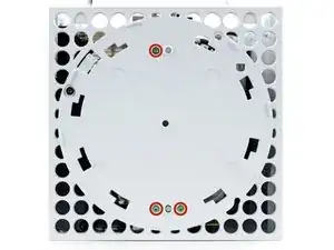
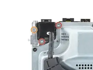
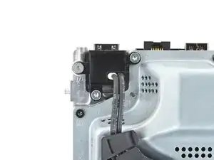
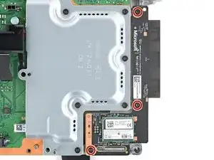
    • Use a T8 Torx driver to remove the three 8.7 mm‑long screws securing the Wi-Fi antenna board.

  39. sRJjUKaHdApFlTXH
    sRJjUKaHdApFlTXH
    4RgZdNCudHDjkfeV
    bxccoepqqUSuxCdf
    • Don't pull up on the antenna board until it's completely disconnected.

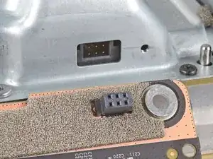
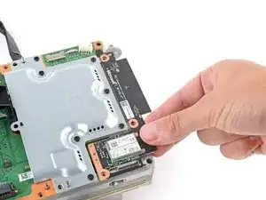
    • Grip the antenna board and pull it directly away from the center chassis to disconnect it.

    • Remove the antenna board.

    • During reassembly, align the board's connector with the port on the center chassis and press to reconnect.

Conclusion

To reassemble your device, follow these instructions in reverse order.

Take your e-waste to an R2 or e-Stewards certified recycler.

Repair didn’t go as planned? Try some basic troubleshooting, or ask our Answers community for help.

Spencer Day

Member since: 14/09/22

88286 Reputation

0 comments