Introduction
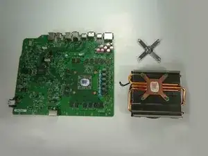
This guide will show you how to replace the heat sink and fan of your Xbox One.
The fan is responsible for keeping the Xbox's processor at a safe operating temperature. Without it the Xbox cannot run and if it is not working properly, the Xbox may malfunction.
Note that this replacement requires you to remove the heat sink and fan from the motherboard. Every time you remove the heat sink you should replace the thermal paste that separates it from the motherboard. Be sure to have replacement thermal paste on hand before reassembling the device.
-
-
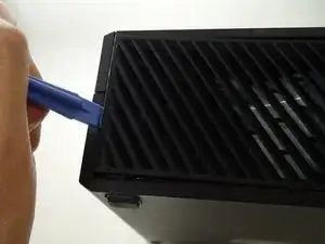
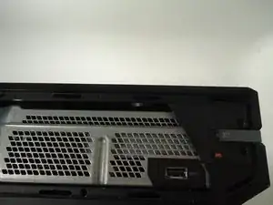
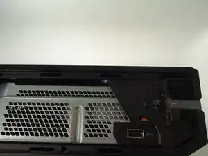
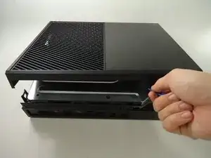
Slide the black angled tab behind the silver button toward the back of the console and set it aside.
-
-
-
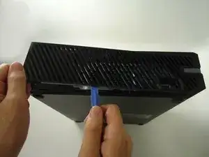
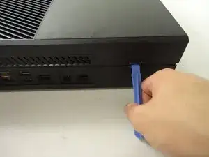
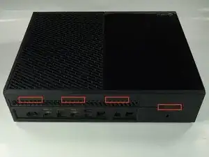
Use a plastic opening tool on the back to pry the top of the case from the bottom. Use an up and out motion to dislodge the clips. There are multiple clips to release on the back and two on the sides.
-
-
-
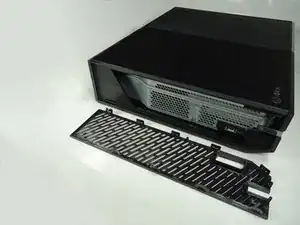
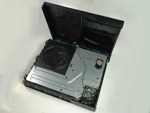
Carefully lift the top of the case, note that there is a wire connecting the front panel to the motherboard. Take care not to break this.
-
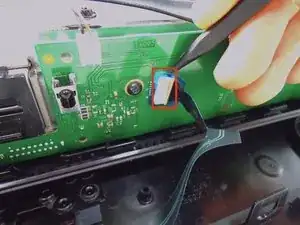
Using a spudger, release the ribbon wire from the front panel.
-
The top case is now free, set it aside.
-
-
-
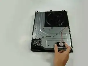
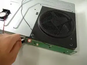
Remove the speaker by squeezing the the tab on the black plastic mounting piece and lifting it up.
-
Carefully unplug the connector from the green front panel board.
-
The speaker is now free, set it aside.
-
-
-
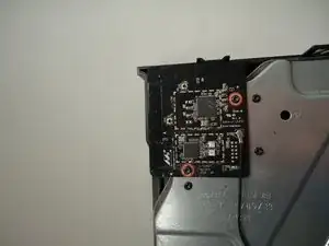
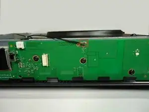
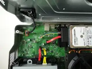
Unscrew the two 8.2mm T-9 screws securing the Wi-Fi board to the chassis.
-
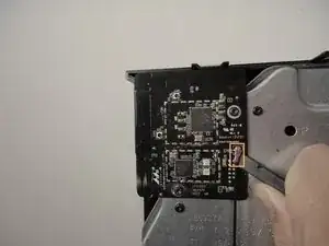
Using the spudger, gently lift the antenna connector from the Wi-Fi board.
-
-
-
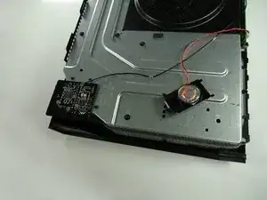
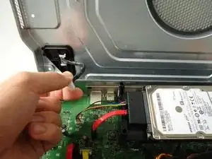
Using a spudger and a motion similar to the previous step, gently lift the antenna connector from the green board on the front.
-
Carefully pull out the clips securing the antenna wire to the chassis, releasing the wire.
-
-
-
Carefully pull the Wi-Fi board straight up to release it from the chassis. The Wi-Fi board is now free.
-
-
-
Remove all eight of the 64.0 mm, T-9 screws labeled C1 through C8 securing the chassis top to the motherboard.
-
-
-
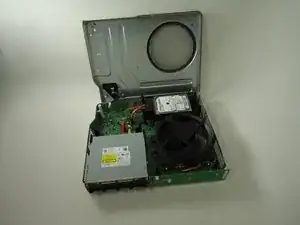
Lift the chassis top, being careful not to break the wire connecting the chassis top to the motherboard.
-
Unplug the connector labeled 3 on the motherboard by gently pulling up.
-
The chassis top is now free, set it aside.
-
-
-
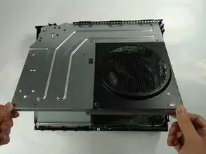
Lift the bottom half of the chassis (motherboard and all) from the bottom half of the black case.
-
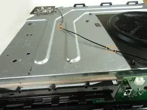
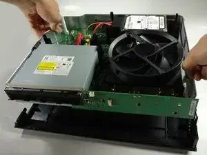
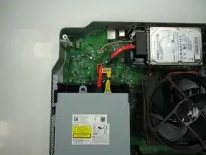
Unplug the red wire connecting the optical drive to the motherboard from its connector on the motherboard.
-
Unplug the yellow wire connecting the optical drive to the motherboard from its connector on the motherboard.
-
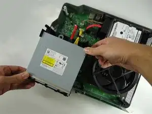
The optical drive is now free, lift it from the chassis and set it aside.
-
-
-
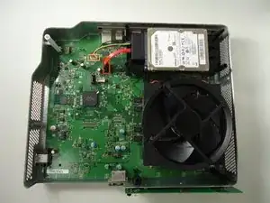
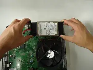
Unplug the red wire connecting the hard drive to the motherboard from its connector on the motherboard.
-
Unplug the multi-colored wire connecting the hard drive to the motherboard from its connector on the motherboard.
-
The hard drive is now free, remove it from the chassis by lifting straight up. Set it aside.
-
-
-
Turn the chassis upside down.
-
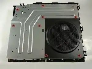
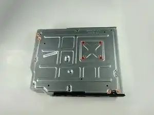
Remove the four black 9.5mm T-9 screws labeled A1, A2, A3, and A4.
-
Remove the four grey 11.0mm T-9 screws labeled B1, B2, B3, and B4.
-
-
-
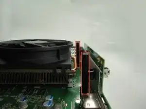
Remove the three 9.5mm T-9 screws holding the front board onto the metal chassis.
-
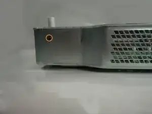
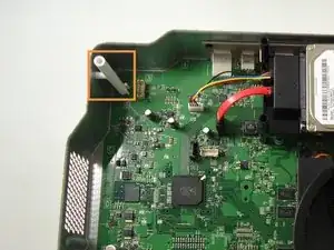
Remove the single 8.2mm T-9 screw holding the white standoff to the metal chassis.
-
-
-
Remove the two black standoffs by squeezing the clips securing them to the metal chassis and lifting up.
-
Remove the white standoff.
-
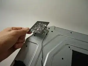
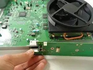
Unplug the front panel board from the chassis. The board is now free, set it aside.
-
-
-
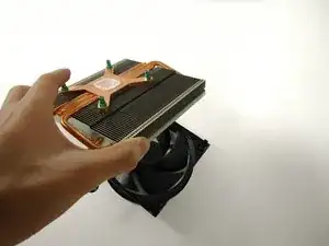
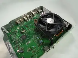
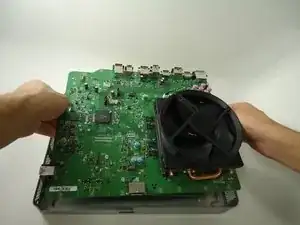
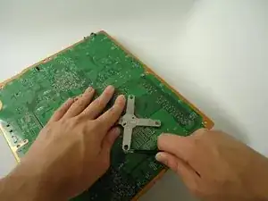
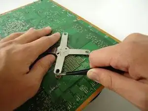
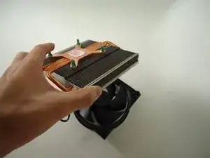
Carefully turn the chassis back over. Grasp the motherboard or the fan and lift the assembly free with the fan and heat sink attached. Set the bottom of the chassis aside.
-

To reassemble your device, follow these instructions in reverse order.
One comment
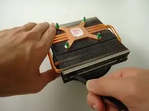
The fan is simply clipped on to the heat sink via 4 clips and can be removed/installed without having to do anything what-so-ever to the heat sink or x-clamp. There are unnecessary steps in this guide big time!
cc178700 -