Introduction

After extended use, the bumper switches may become less responsive even if the bumpers themselves are not damaged. This guide will demonstrate the disassembly, replacement, and reassembly of the controller to replace these switches.

  1. ZGBtdWtVTLh1cK6V
    ZGBtdWtVTLh1cK6V
    VPXrftJAGKBDwvFv
    DGt2aGUPXITXHDxA
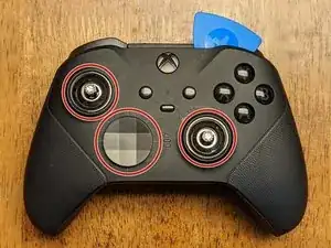
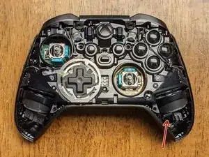
    • Slightly differing from the previous model, the faceplate needs to be removed before anything else. Begin by removing the joystick caps and d-pad cover.

    • Once these are removed, you'll need to begin working an opening tool along with the picks around the faceplate starting at the top-left or top right.

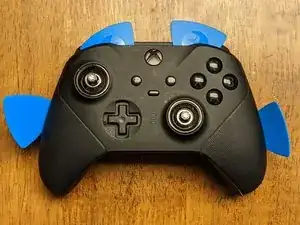
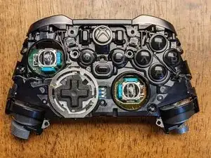
    • Slowly work around the faceplate to loosen the clips using primarily the plastic opening tools to prevent any damage to the faceplate & internal components.

    Starting center to sides from top, then center to sides from bottom worked for me.

    Robert Cole -

  2. 2AYh4w5NlcEKooTG
    2AYh4w5NlcEKooTG
    dXMJEBpqAJR11hUL
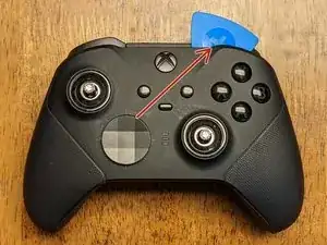
    • This is the only part in the face removal I would suggest using the metal spudger as you'll need a little more leverage to release the adhesive holding the faceplate down.

    • Insert the metal spudger in the area located but only as far as you need to get some leverage to pry the faceplate up. Work cautiously and slowly as this can easily damage components.

    • The adhesive is located in two places and because this doesn't seal the device together for IP-67/68 requirements, it isn't necessary to replace.

  3. u1CrZREhmr3ZXNx2
    u1CrZREhmr3ZXNx2
    iBT4caHepZSMhURK
    • The joysticks are screwed onto the stem of the potentiometers and will need some convincing to remove. These will need to be twisted counter-clockwise to remove with either of the following methods:

    • Method 1: Using a joystick cap - try this first regardless as it has less possibility of damaging the device. Insert one of the joystick caps to each of the joysticks and attempt to twist by hand. If they are too tight, proceed to the second method.

    • Method 2: Using pliers - using as little force as necessary to prevent slipping, squeeze the joystick near the base, where the bevel allows for a "flat edge" that the pliers can grip. Once these are loose, revert to method 1 to continue the removal.

    YOU WILL BREAK THE ANALOGS if you force them with pliers! Symptom of them breaking: they start spinning around endlessly, with some resistance and never come undone. Please use a heat gun (300C was enough in all cases of me) to heat up the dome stem and then it comes undone very easily. The problem is some industrial grade loctite on its threads.

    tomaspuzis -

    Is there anyway of getting them off once you break them ?

    nicholasfawcett -

    Yes, this step is hell. Can't remove sticks correctly, broke one (symptom described above), and second one not working when I put everything back. Why is it so hard to disassemble....

    Frederic Esnault -

    Pliers are a bit too much in my opinion, a bit too easy to strip something essential or gouge the metal, and there is Loctite involved from the factory here also. I'd recommend using the long thumbstick extender locked onto the stick, since it has the rubber grip tip and is longer it should give you enough torque to get the threads unstuck and unscrew the thumbsticks. Use a slight downward force as you turn the stick to make sure the grooves don't strip on either the extender or the stick piece. At least try this first before moving to pliers.

    just chris... -

    Wish I read the comments first.. I ended up damaging my right stick but was able to move the analog guts back into place and get it functional again. 1/4" socket or box end wrench was a little small, but slight downward pressure gave it grip to screw.

    Attempting to just use the analog stick resulted in me shearing the bond between grip and metal and it's all bumpy now.

    Robert Cole -

    DON'T USE PLYERS!!!! I now have to buy and solder on 2 new analog potentiometers for my controller this is the second time iFixit's "teardown" has caused me to break some ones stuff luckily this time its mine.

    Spunken himer -

    Read the comments and still had to use pliers to get the stick off… screwing in the stick during reassembly seems critical to give it clearance from the plastic face above. To have enough clearance it needs to be super tight again (beyond screwing in by hand) and this is where I broke the tiny screw threads along the stick. It’s clear this was intentionally manufactured to be difficult to repair

    Blake Swanson -

    I used the tall stick and a towel to maintain grip. Slow form pressure and the sticks loosened pretty easily with zero damage.

    Gregory Haberek -

    I had much success with the heat application method and tall thumbstick. I just used a cheap harbor freight heat gun set to low and held about 8 inches away so I didn't risk melting plastic. After about 20 to 30 seconds of applying heat it was much easier to break them loose.

    Adam Bellerive -

  4. rAtjBMNXyTKyJnb3
    rAtjBMNXyTKyJnb3
    kPGX3s5NSX6eTTdX
    23nt4LeFwPOKTYO1
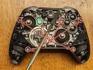
    • Remove the six T-8 Security screws holding the front and the back of the controller together. Note: one (highlighted green) is covered by a white paste/sticker that crumbles when removed; this lets you know if someone has previously disassembled your device.

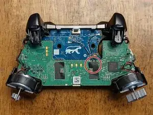
    • Once the screws are removed, you can insert a spudger under a vibration motor to provide a little leverage to separate the front from the back of the device.

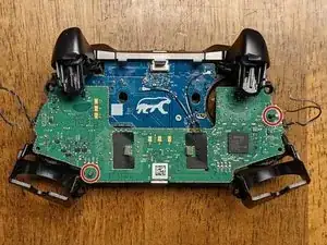
    • The third image shows the front assembly removed from the back cover.

  5. iQVBXK2q1aiYDLHk
    iQVBXK2q1aiYDLHk
    S5kY1hcNFjTam3qL
    LOqPZnF3glAOAObq
    • Begin by peeling back the tape (tweezers might help) covering the connection on the green board.

    • While holding the tape back, insert the plastic pointed spudger under the connections, and the force of pushing the spudger under them should be enough to release them from the board.

    I’m having trouble reconnecting these cables back to the motherboard.

    Joseph Samuel -

    Hold the cable over top of the connector with one hand and use your fingernail to apply firm even pressure until you feel the connector reseat.

    Daniel Babin -

    I broke one of these cables accidentally, how are they called?, need to buy it.

    Rafael Cordoba -

    Hey what do these actually do? I think I forgot to reconnect them during reassembly, but the controller seems to be working just fine?

    Vilém Dojiva -

    I think they're antenna wires just based on the connector design; I assume they allow for a better connection in either bad RF environments or at range. A connection will often persist for devices that require an antenna but will connect significantly better when they're attached.

    Wayne Roberts -

  6. EkSQY1D3oRRwO22e
    EkSQY1D3oRRwO22e
    5Iq2cMchMfMdBlfX
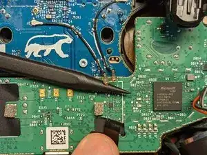
    • The wires will need to be desoldered from the board, and will be replaced later for reassembly.

    • Note: each pair of wires has the black cable soldered to the lower connection; keep this in mind for the reassembly if the pictures from this guide aren't nearby.

    • Note: You may be able to get away without desoldering these, depending on what you need to reach (credit to @bikemerlin), but due to the simplicity and fragility of these connections, I would suggest removing them to prevent additional damage.

    • Some of the solder in this controller requires a very high temperature to release. I had mine set to 450 C, however you may be able to remove it at a lower temperature.

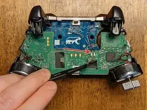
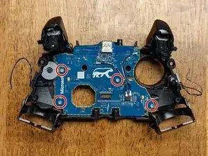
    • Remove the two T-6 screws from the board near the vibration motors.

    On reassembly, after the board is aligned over the pins, and screws are started, press in the center of the board mother board to plug in the connector from the motherboard to the button board.

    Andrew Kruse -

    Getting in here to clean a sticky Y button, i was able extricate the button board without de-soldering any of the wires. Unclipping the black/gray wires from their most outboard clips and then being extremely careful not to bend any where they connect to the motherboard, you can flip the whole motherboard out of the way, giving enough access to the button board.

    BikeMerlin -

    Yep, it should be possible to do it without desoldering. Some of the other main board connections are quite a bit more difficult to desolder, but these are relatively easy in comparison, so I would still suggest removing them to prevent extraneous damage if at all possible; assuming you have the appropriate tools, of course!

    Wayne Roberts -

    Was the wire soldering done by you on re-assembly, or did it come like this?

    SonarTech -

    That's my bad soldering job - I had a time with some desoldering and got a bit frustrated at times. These connections weren't bad to work with, but that doesn't prevent me from being bad at soldering lol

    Wayne Roberts -

    Note: T6 screws are not security bits.

    Brian Capshaw -

    If that's in regard to the tool requirements, I think the tools I could choose from in the UI either didn't have it or there were T6S somewhere else in the controller, however, I don't see what you're specifically referencing. For anyone needing the tools to do this, T6S (security) tools will work with T6 hardware, but not the other way around if you encounter T6S hardware and only have a T6 bit.

    Wayne Roberts -

    Does anyone know what the IC with W8 attached at FT21 is? This IC somehow sheared off while I was desoldering black/gray combo, no clue how that was possible since I never touched it. But I'm definitely going to swap the component out either way.

    TrickyRich -

  7. WAEwDFxSpsEAX3XV
    WAEwDFxSpsEAX3XV
    hi2LZMCjIN2tqLvl
    • Begin removing the motherboard by sliding it up along the pins (as noted in the picture). The left side will need to be lifted off of its pin and the board rotated counter-clockwise at a slight angle before it will be able to slide the remaining distance off of the right (longer) pin.

    • The triggers will flex up a bit which allows a little extra room for the board. As with everything else in this disassembly, use caution and patience to prevent damage to any of the components.

    • Once the motherboard has been removed, you may have already noticed the headphone jack has moved or fallen. If it hasn't remove it from the board now.

    Be careful as you slide up the motherboard, as there is a connector between them, and can easily shear the connector on one side if not slow and careful.

    Adam Coulter -

  8. 1grRCJ5vihjsMte4
    1grRCJ5vihjsMte4
    dm2e4EP5SrxtqOMJ
    shP1EPyS6lZRo1Rf
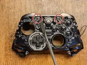
    • There are two tabs holding the retainer for the bar in place. Gently pop these toward you with a spudger and they'll slide up from their own tension. Note: the retainer will likely stay attached to the bumper assembly, but must be removed from the main controller assembly before proceeding to the next step.

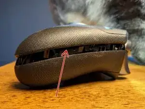
    • Once the retainer has been released, again use the spudger to gently pry the buttons outward and upward (in the direction of the arrow in the image) which will release them from another clip. Do this on both sides.

    • As user Shane Muir has pointed out, please be careful due to the fragility of the retainer in this step. It can easily be broken.

    It’s worth emphasizing that these retainers are fairly easy to break on accident. Be extra gentle when removing or replacing the bumper bar.

    Shane Muir -

    Thanks for the advice; I’ve updated the guide to reflect!

    Wayne Roberts -

    So... I did break one.. is there a replacement?

    Alexander Lima -

    The bumper bar comes as an assembly from everywhere I've seen, so it's likely you'll need to purchase a new assembly or scavenge one from a parts controller.

    Wayne Roberts -

  9. LoQlLvRAIC2AmNuD
    LoQlLvRAIC2AmNuD
    KaDm1HhsPPhjklNj
    • Remove the four T-6 screws holding the daughterboard to the controller frame. Keep in mind this board holds all of the remaining buttons in place, so be careful none of them are lost when removing this.

    • Note: All of the buttons have clips surrounding them that prevent any of the buttons from being installed in the wrong place; be sure not to force any of them into a different location when reassembling the device.

    • When reassembling, do not force anything into place as this could indicate something has been installed improperly.

    • That's it! Hopefully this guide allowed you to access any components that need replacing.

    This is also known as the "button board"

    Andrew Kruse -

    Talking about every step except the D pad. I have a problem only with the d pad

    jeffrey lepage -

    This is a disassembly guide and to this point, the directional pad has already been removed. What problems are you encountering?

    Wayne Roberts -

    Mine is brand new, BUT, the left joy stick STICKS to the left full on a lot. Sometimes to the right as well.

    There's nothing causing it to recenter.

    No I can't take it back, messed that up like a moron I'm stuck with it.

    Ron Godwin -

    The joysticks are an absolute pain to remove, but if you can remove them, they are easily replaceable. Basically, the solder on all of the connections must be melted concurrently for its connection to the board to be removed. If you manage to do this, you've done the hardest part; beyond that, you need only to solder each connection as you would any other. The caveat is there are unique deadzones to each joystick assembly that either need to be matched closely or calibrated with additional hardware as I don't believe MS has or ever will release any way to calibrate them.

    Wayne Roberts -

  10. mk25hnqdsAwP14Yl
    mk25hnqdsAwP14Yl
    1YhoB5twQ3WTqLS3
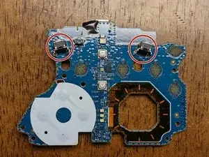
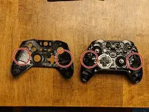
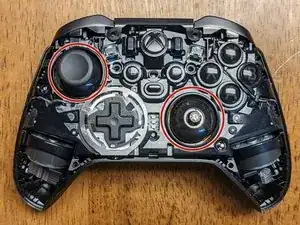
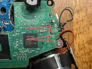
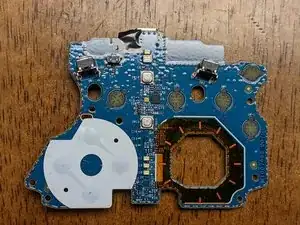
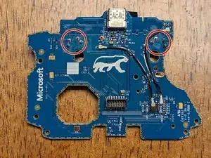
    • The circled areas on the image indicate the switches and their respective connections that will need to be desoldered and replaced.

    • If you don't have access to a desoldering gun, this will be much easier by cutting the old switches into pieces. Take care to leave as much of each of the pins as possible to provide something to pull against for removal.

    • The switches are shaped so they must be pressed into the socket with a decent amount of force; this is what makes the removal so difficult.

    Flux and fresh leaded solder on each joint will bring down the factory unleaded solder temp. This allows for a much easier removal for any electronic component. Users most time have frustrating encounters trying to remove factory unleaded solder(has a higher melting point). Also should have a solder tip relitivly same size as solder joint. Wic works fine after adding the fresh solder.

    Damian Hernandez -

    I've been learning that out of experience lately! I wasn't for sure if it was a fluke so I didn't want to offer it as advice, but it seemed to be working so far. Thanks for the tip, Damian!

    Wayne Roberts -

    • Insert your soldering iron tip inside the hole and use the pump from the other side to remove all of the solder.

    • Unfortunately, I didn't take pictures of this process, however, this is where the desoldering pump becomes a necessity. The new switches will need ample room to be inserted in the holes, so you'll have to make sure there is no remaining solder in them.

    This part is where I got stuck. There is no way to remove the solder. For the back holes, they don't even melt, even with flux and more solder. I'm giving up on fixing it just because i can't remove the solder. Any help on this would be appreciated.

    Frederic Esnault -

    It's been a while since I've gone through this process, but if I remember correctly I ended up using quite a bit of fresh solder to loosen up the OEM solder. I don't remember the temp setting I had my soldering gun, but it was way hotter than I needed to melt my replacement solder. Try to crank up the temp a decent amount and see if that helps; that and a little extra time sitting on those connections might help. Good luck!

    Wayne Roberts -

    Solder wick dipped in flux will also works. Either wau, be sure to use an iron set to around 420C or so due to the lead-free solder used.

    Sheldon Erickson -

    • Once the switches have enough clearance to be inserted, they will hold themselves in place as they have enough outward tension to do so.

    • Add new solder to the connections.

    • Depending on the replacement switches you purchased, you may need to shave the arm down that pushes on the switch. This is the part of the bumper that extends downward and physically presses the switch itself.

    • This was required for my device as I had leftover Xbox 360 switches that seem to be more tactile and durable than the Xbox One variants.

Conclusion

To reassemble your device, follow these instructions in reverse order.

Wayne Roberts

Member since: 28/07/21

1380 Reputation

2 comments

decent guide, except for step 13 imo. these switches are dirt cheap, i can't see it being a good idea to modify the part of the bumper instead of ordering the proper switch.

bmx6454 -

My shell and my right bumper broke, bought a whole replacement will try when it come, though the indications are clear and simple to follow

Rahian Bedrouni -