Introduction
Get back to your gaming by replacing your Xbox 360 wireless controllers logic board.
Parts
-
-
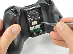
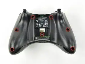
Depress the battery release button on the top of the controller.
-
Remove the battery holder from the controller.
-
-
-
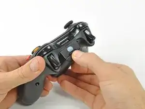
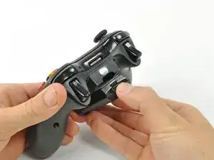
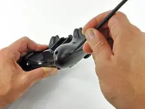
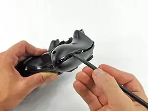
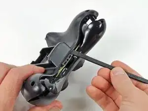
Insert a spudger between the front and rear cases, near the headphone jack.
-
Rotate the spudger toward the front of the controller to pry the two cases apart.
-
-
-
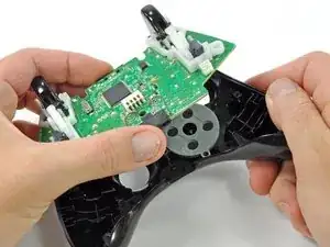
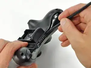
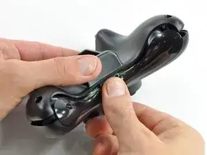
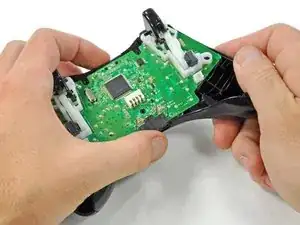
Grasp the controller by the battery compartment and the headphone jack.
-
Lift the battery compartment away from the headphone jack, separating the rear case from the front case and logic board.
-
-
-
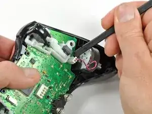
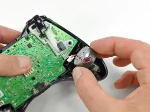
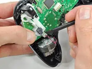
Use the flat end of a spudger to remove the vibration motor cable, moving it upward from its socket on the logic board.
-
Lift the vibration motor out of the front case.
-
-
-
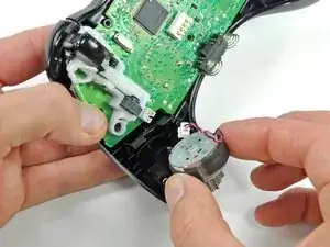
Remove the vibration motor from the other side of the controller using the same method previously described.
-
-
-
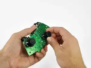
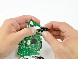
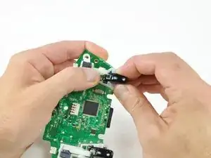
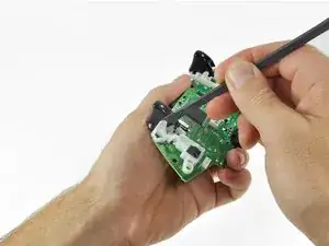
Using your thumb and forefinger, push the left trigger toward the right side of the controller. Simultaneously push the trigger control arm in the opposite direction.
-
Push the trigger arm downward.
-
-
-
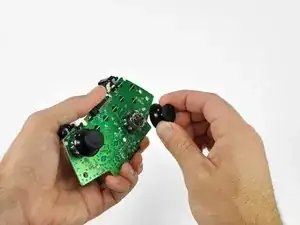
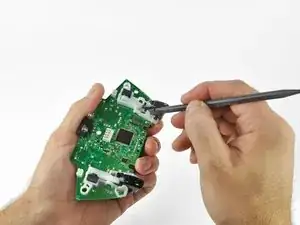
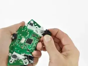
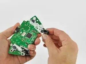
Insert the edge of a spudger in between the trigger and the trigger assembly near the left edge. Pry the housing away from the catch on the trigger.
-
Using the previously described technique, pry the housing on the right edge away from the trigger.
-
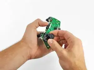
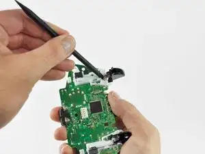
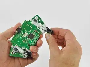
Rotate the trigger away from the logic board, past its housing.
-
-
-
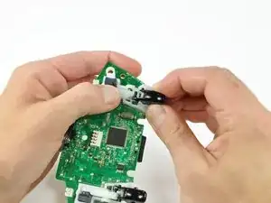
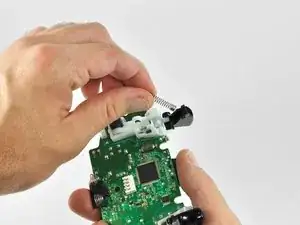
Using a spudger, pry the trigger spring off its peg on the trigger housing.
-
Pull the trigger spring out of the trigger.
-
-
-
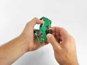
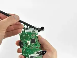
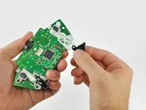
Slide the trigger toward the right side of the logic board, and rotate it clockwise.
-
Remove the right trigger from the logic board.
-

To reassemble your device, follow these instructions in reverse order.

6 comments
Does it matter which side the motors are returned to? I think I may have swapped positions with my two motors.
brian -
Any guides for troubleshooting the test points on the board as to determine why the left trigger doesn't aim during gameplay? I've replaced the potentiometer with a brand new one but still nothing, everything else works perfectly …thoughts?
bad connection down the Vdc supply, gnd, or sense pin paths? Or a blown channel on the ADC that reads the potentiometer and converts the value to digital. If the ADC is integrated inside the main chip, its toast. Its also possible another component along the signal path may be faulty. Like a capacitor gone short for some reason. Basically its break out the multimeter and start poking stuff time.
Tank R -
I don't need a removal guide I need a diagram that shows me how to put the trigger on a button on top so a child with deformed fingers can use it. The triggers apparently have hall type sensors.
jim27601 -
I havent been inside my official remote yet, but if the unofficial ones Ive scrapped and/or repaired are any indication the triggers are potentiometers, not hall effect sensors. If you're fine with simple binary control (ie, on off, and not the analog sweep of values) then just wire the center pad and what ever side the wiper moves towards (whichever side drops in resistance when going to full deflection) to a button. If that doesnt work, try center and the other pin.
Tank R -