Introduction
The bearing of this steering wheel is notorious for wearing down and being very loose. A metal ball bearing is a nice upgrade. There are multiple videos on youtube that are available as reference, and some made reference to use a machine shop, but here is a simpler solution using common hand tools.
Parts
-
-
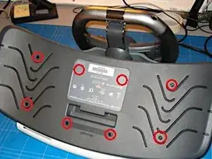
Remove 8 screws from the base (two are covered by the sticker), using a TX10 security screwdriver (i.e. with the security hole at the top)
-
-
-
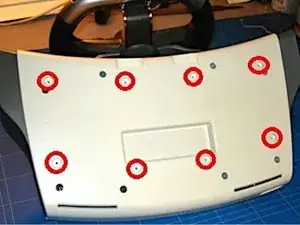
Remove the additional 8 screws from the back of the wheel assembly, again, using the TX10 security screwdriver.
-
-
-
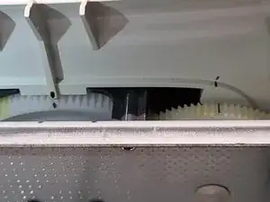
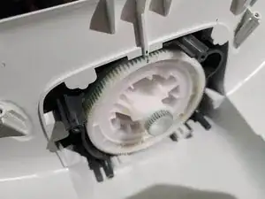
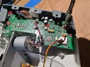
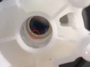
Turn steering wheel fully clockwise or counter-clockwise until it hits the stop (picture shows the stop).
-
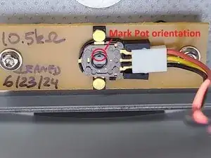
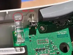
Mark the main gear position as shown (Gear that is attached to the motor is also marked, but that is not critical).
-
Mark the position of the potentiometer.
-
-
-
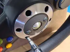
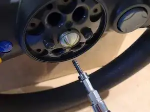
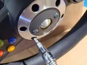
Remove the six 3/16th hex bolts, and then remove the faceplate.
-
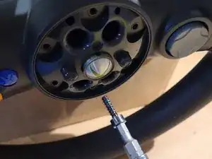
Remove the four 3/16th hex bolts holding the steering wheel in plane.
-
-
-
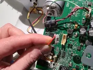
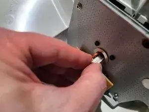
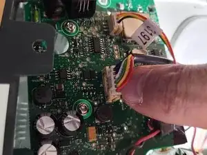
Disconnect the steering wheel connector. Note: older versions of the wheel may have more than one connector.
-
Remove the steering wheel from the stem, and guide the connector through the center hole.
-
-
-
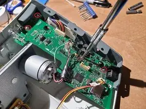
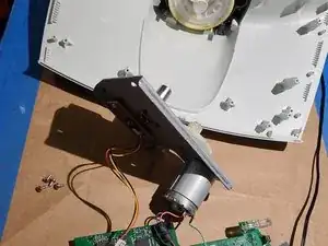
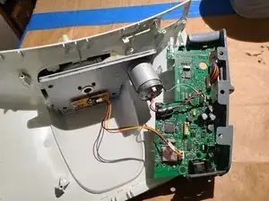
Remove four TX10 screws holding the motherboard in place.
-
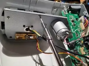
Remove four TX screws holding the motor back plate.
-
Pull the motor plate and motherboard out of the way.
-
-
-
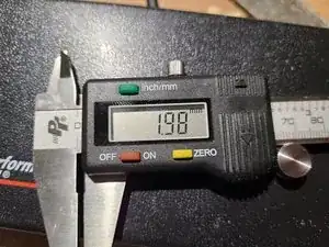
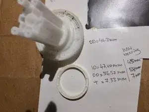
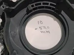
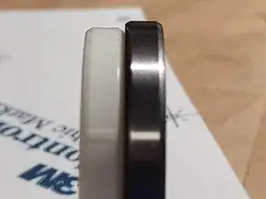
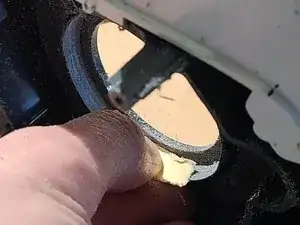
OPTIONAL - measure the old and new bearing dimensions.
-
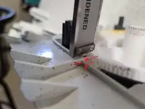
Notice that the outer ring holding the bearing will need to be ground down by 0.5 mm (total of 1 mm more room needed to fit the new bearing.
-
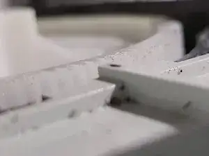
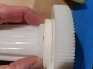
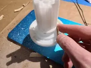
the stem of the main gear is also too thick, so it will have to be ground down as well.
-
-
-
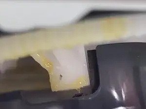
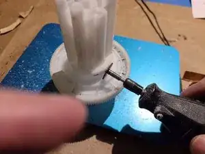
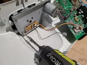
Wear a face mask, and then using a dremel, carefully remove some of the nylon all the way around until the bearing slides all the way down. This took about an hour. The stem was mounted on a vertical stick so it could be rotated while using the dremel.
-
Use 150 sandpaper to smooth out the edges of the dremel wheel.
-
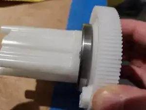
Verify that the new bearing fits square to the mark of the old bearing. Note that the mark will be worn down by the dremel , so keep re-marking it with the old bearing.
-
-
-
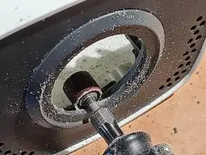
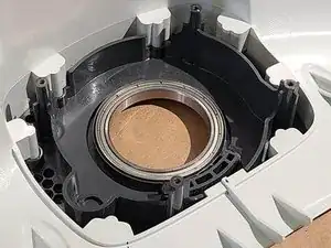
Using the dremel in a circular pattern, wear down the lip for the outer rim of the bearing. Go slowly as there is not a lot of material.
-
Once the bearing fits tightly, then use 150 sandpaper to smooth out the dremel marks.
-
Vacuum an excess plastic and press fit the bearing. Not that the lip is quite thin, so do not force too hard. If you cannot get the bearing in, then grind down some more instead of stressing the lip.
-
-
-
Clean and trial fit to make sure the gear height above the case is the same as before.
-
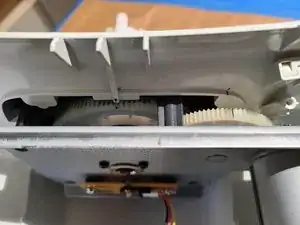
Grease the main gear and re-install, with the mark aligned (the gear should be resting against the stop).
-
Guide the motor plate in place, making sure that the potentiometer mark is also aligned. If it was disturbed, the gear of the potentiometer on the back side may need to be rotated slightly before engagement.
-
-
-
Tighten (do not over-torque) the four TX10 screws for the motor mounting plate.
-
Insert the motherboard at a slight angle, getting the LED light aligned first, and tighten (do not over-torque) the four TX10 screws for the motherboard.
-
-
-
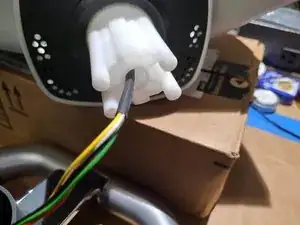
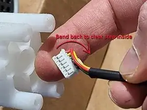
There is a step inside the center hole of the stem. Bend the connector back slightly before inserting.
-
Plug the connector back into the motherboard
-
-
-
Tighten (do not over-torque) the four longer 3/16th hex bolts holding the steering wheel to the stem.
-
Install the faceplate.
-
Tighten (do not over-torque) the six shorter 3/16th hex bolts .
-
Re-assemble the rest of the unit (see disassembly guide)
-
To reassemble your device, follow these instructions in reverse order. Do not over-torque screws.