Introduction
-
-
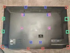
Philips #2 screws, 15.0 mm
-
Philips #2 screws, 29.5 mm
-
Philips #2 screws, 8.0 mm
-
VESA mount points (M6, 10mm, 400mm * 200mm)
-
-
-
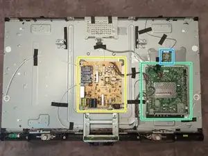
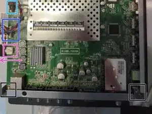
4-pin connector to T-Con board. Depress plastic clip at left side and wiggle connector side to side slightly to remove.
-
13-pin connector to Power Supply board. depress plastic clip at left edge and wiggle connector side to side. May need to pry up top/bottom edge with flat head screwdriver; alternate gradually.
-
42-pin connector. Pry up with flat head screwdriver on left/right edges, alternating gradually.
-
Grounding clip. Using a poking tool, press at center to release catch and pull clip in indicated direction.
-
-
-
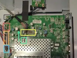
8-pin connector. Depress clip and pull connector upwards from board.
-
10-pin connector. Depress clip and pull connector upwards from board.
-
4-pin connector to speakers. Depress Clip and pull connector in indicated direction.
-
mounting screw. Philips #2 @ 6mm
-
-
-
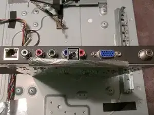
If your replacement board is missing the bottom I/O shield, you can remove the I/O shield from the old board by removing the marked screw (Philips #2).
-
To reassemble your device, follow these instructions in reverse order.