Introduction

Use this guide to remove a broken or defective LCD & Digitizer in your Sony Xperia Z4.

Opening the Sony Xperia Z4 will damage the waterproof seals on the device. If you do not replace the adhesive seals, your phone will function normally but will lose its water protection.

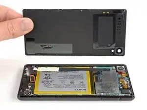
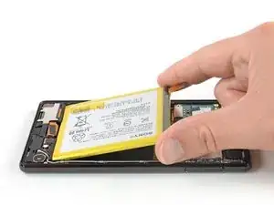
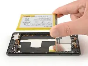
Due to the phone’s design, you must remove the lithium-ion battery to access the display cables. If the battery was deformed during removal replace it with a new one—reusing a deformed battery is a potential safety hazard.

Before disassembling your phone, discharge the battery below 25%. The battery can catch fire and/or explode if accidentally punctured, but the chances of that happening are much lower if discharged.

Note: This guide instructs you to replace only the screen while leaving the original frame and motherboard in place. However, some replacement screens for this phone come pre-installed in a new frame (a.k.a. chassis), which requires a very different procedure. Make sure you have the correct part before starting this guide.

You’ll need replacement adhesive to reattach components when reassembling the device.

  1. 5oML3lClGeBOgCyH
    • Before you begin, switch off your phone.

    • Apply a heated iOpener to the back of the phone to loosen the adhesive beneath the back cover. Apply the iOpener for at least two minutes.

  2. rO5KPkb54vQHicHW
    rO5KPkb54vQHicHW
    V6pWUENhTkCnwMoN
    WTgpHCC2wqSFSr6P
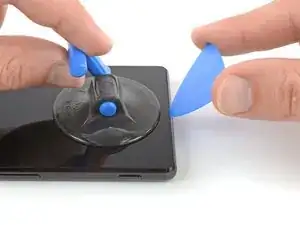
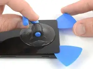
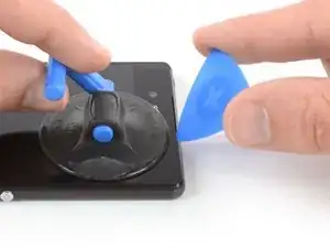
    • Secure a suction handle to the bottom of the back cover, as close to the edge as possible.

    • Lift the back cover with the suction handle to create a small gap between the cover and the frame.

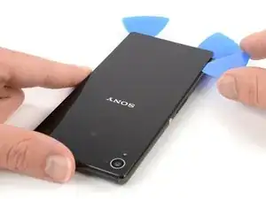
    • Insert an opening pick into the gap.

    • If you have trouble, apply more heat to further soften the adhesive. Follow the iOpener instructions to avoid overheating.

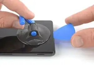
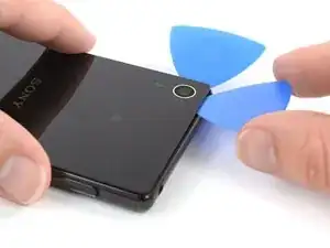
    • Slide the opening pick to the bottom left corner.

  3. HLAmqbjFYetjBFnv
    HLAmqbjFYetjBFnv
    aidXeC32BOb1YPGc
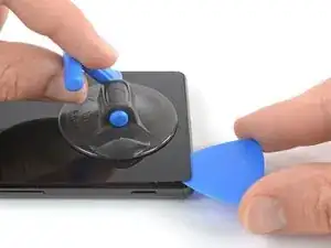
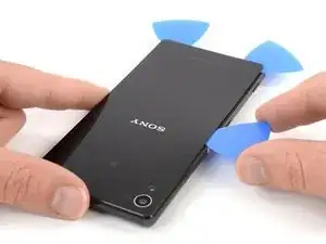
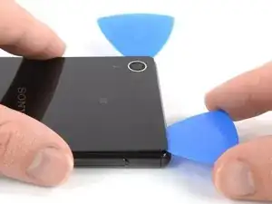
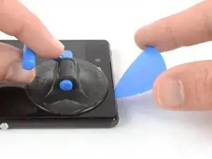
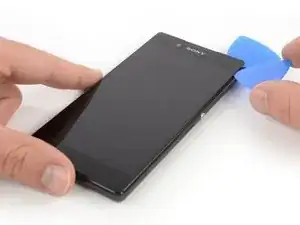
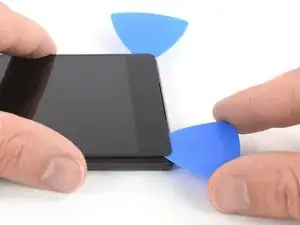
    • Insert a second opening pick and slide it to the bottom right corner to cut the adhesive.

    • Leave the opening picks in place to prevent the adhesive from resealing.

  4. GUckhiSqTEcblBEX
    GUckhiSqTEcblBEX
    CJPOaFwRSyLylKRE
    jjXYSVG6dYhuUCv1
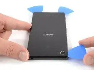
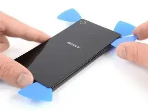
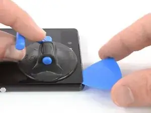
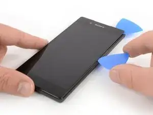
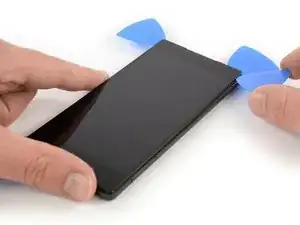
    • Insert a third opening pick at the bottom left corner.

    • In the next few steps whilst cutting around the rear camera make sure you only use the tip of the opening pick to avoid smearing the lens or damaging the camera.

    • Start to slide the tip of the opening pick from the bottom left corner along the side of the phone to cut the adhesive.

    • Leave the opening pick in its place at the top left corner to prevent the adhesive from resealing.

  5. G2mudFvkD5ELQeKN
    G2mudFvkD5ELQeKN
    cfTvfQ1JFqFFkfIR
    • If the adhesive becomes hard to cut it most likely cooled down. Use your iOpener to reheat it.

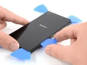
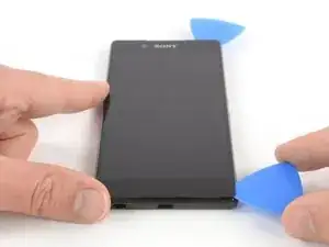
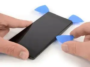
    • Insert a fourth opening pick under the top left corner of the back cover.

    • Slide the opening pick along the top edge of the phone to cut the adhesive.

    • Leave the opening pick in the top right corner to prevent the adhesive from resealing.

  6. dprvGBVBCBhiVeDW
    dprvGBVBCBhiVeDW
    FQts5sC2g3LRQiUp
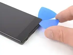
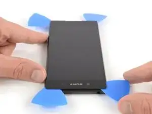
    • Insert a fifth opening pick at the top right corner of the phone.

    • Slide the opening pick along the right side to cut the remaining adhesive.

  7. wUjfjgZCBZSAcmQK
    wUjfjgZCBZSAcmQK
    JVxRoq4TCrCRM2Pf
    • Lift and remove the back cover.

    • After installing the back cover, apply strong, steady pressure to your phone for several minutes to help the adhesive form a good bond, such as by placing it under a stack of heavy books.

  8. LJBSX2uFYffJm1PN
    LJBSX2uFYffJm1PN
    SeCZnEy5ooOcTWsj
    aaeEPTVJaITvhqlG
    • Use a pair of tweezers to carefully peel the adhesive strip off the mother board and the battery and remove it.

  9. IG2isBsd5xbLxG5Z
    IG2isBsd5xbLxG5Z
    CmDU2MFF3rdibFIZ
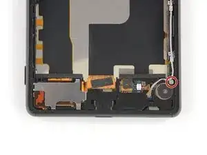
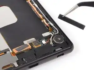
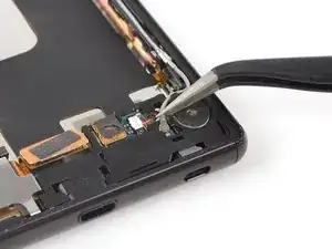
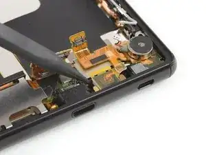
    • Use a pair of tweezers to peel the black adhesive strip off the battery connector and fold it out of the way.

  10. yy5jVkYkTflpHGeT
    yy5jVkYkTflpHGeT
    YaApWkqqvpdFFYrV
    • Use a spudger to pry up and disconnect the battery connector.

  11. F36Kjd4d3ApHRpQd
    F36Kjd4d3ApHRpQd
    rP1hGnrfOCnF23Lg
    YsGnHDah2OK2iUY6
    • Use a pair of tweezers and grab the pull tab at the top right corner of the battery.

    • Pull out the adhesive strip with a pair of tweezers.

    • Make sure you pull out the strip in a slow and steady motion and in a flat angle. To prevent the adhesive strip from ripping, it is helpful to twist the strip around the tweezers.

    • In case one of the adhesive strips rips and it’s not possible to pull it out completely, you can use high isopropyl alcohol (>90%) and/or a heated iOpener to loosen the adhesive. After the adhesive is soft enough use a prying tool such as an opening pick, a plastic/playing card or a spudger to carefully pry out the battery.

  12. YlsiDL6VEV2Sslem
    YlsiDL6VEV2Sslem
    RKJEOYEVUeD6Bdxr
    CN61Q3fFXEWMsUIT
    • Repeat the previous process with the adhesive tab next to the battery flex cable.

  13. RxXLs1SYVVm33cF4
    RxXLs1SYVVm33cF4
    qOBS6inb3fNQHyVH
    • Use an opening pick to pry the battery out of its recess until you can get a good grip.

  14. tRKNMXVmKrHb1BKN
    tRKNMXVmKrHb1BKN
    gAXsFCBHkMGZVKyQ
    • Remove the battery.

    • Do not reinstall a damaged or deformed battery, as doing so is a potential safety hazard.

    • Remove any remaining adhesive from the midframe, and clean the glued areas with isopropyl alcohol and a lint-free cloth before applying new adhesive.

  15. PJ4M5TVvE3KK5BaQ
    • Remove the Phillips #00 screw (3 mm length).

  16. VuX2UJbEFVytXYEu
    VuX2UJbEFVytXYEu
    m5VQBEjapl3s6TdL
    • Use a pair of tweezers to peel off and remove the foam pad on top of the daughterboard.

  17. RTGX54Z2SqsoccVj
    RTGX54Z2SqsoccVj
    nuO6YZ6x3VAZgkQQ
    • Use a pair of tweezers to pry up and disconnect the antenna cable.

  18. vaGvl5CLGXeaVmW4
    vaGvl5CLGXeaVmW4
    1MFbTqPQfZbaVkRS
    • Use a spudger to pry up and disconnect the vibration motor connector.

  19. jWLCvfBR1VCEjoqR
    jWLCvfBR1VCEjoqR
    nKfHmNyUuxZODiBB
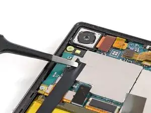
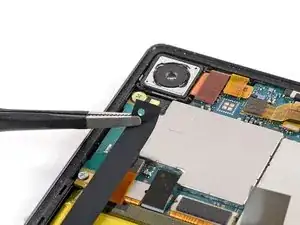
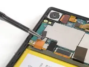
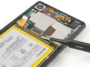
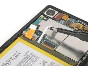
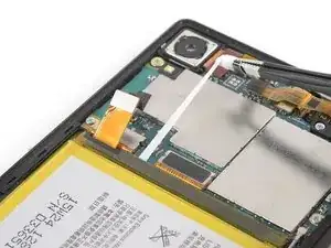
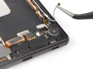
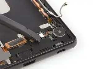
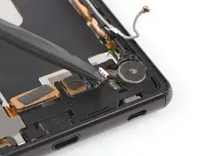
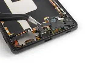
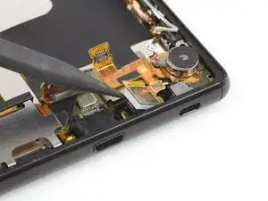
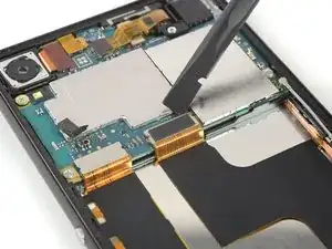
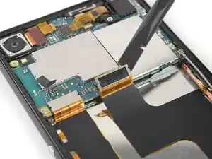
    • Use the flat end of a spudger to pry up and disconnect the small main flex connector next to the vibration motor connector.

  20. XDj2dMDELKdFhQry
    XDj2dMDELKdFhQry
    UnI2JCiQK6XwIOrM
    5MH1aRjbKqCEEPUk
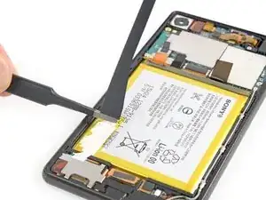
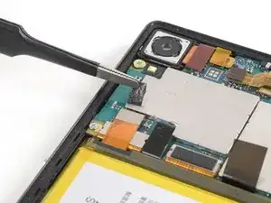
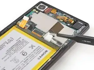
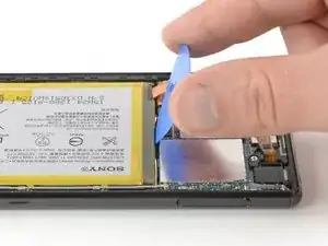
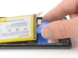
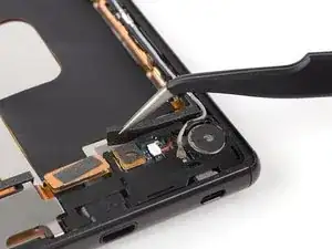
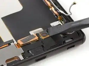
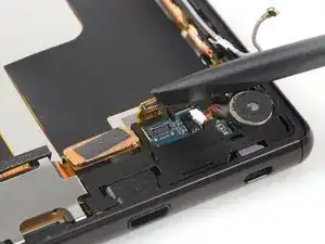
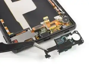
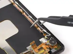
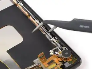
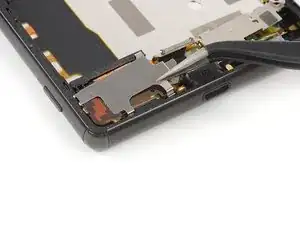
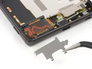
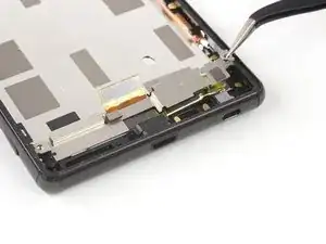
    • Lift the daughterboard cover using a pair of tweezers or a spudger by prying it up from its left side.

    • Remove the daughterboard cover carrying the daughterboard.

    • In case you only want to replace the daughterboard you can easily separate it from the plastic cover with an opening pick or a pair of tweezers.

  21. IyrDtDx1vHBRBgy3
    IyrDtDx1vHBRBgy3
    F2dAvuOCAJVhNQbb
    • In case you only want to remove the loudspeaker and/or the left side button flex cable including the charging port and the loudspeaker cover, jump to this step.

    • Use the flat end of a spudger to pry up and disconnect the main flex cable connector.

  22. SSTDMMeIM6yJmGTg
    SSTDMMeIM6yJmGTg
    SuYCBWSYeiTy4wQ3
    • Use the pointed end of a spudger to lever the microphone out of its recess.

  23. MgmdVcuBy6psvYgt
    MgmdVcuBy6psvYgt
    JJUr2MKE2KpGfTyR
    • Use a pair of tweezers to pry up and disconnect the upper connector of the antenna cable.

  24. QKHoUGSDM6TjaArN
    QKHoUGSDM6TjaArN
    EsCEsrKDkBVsMWIq
    • Use a spudger to pry up and disconnect the main flex cable from the motherboard.

  25. WiVihtnqAgUIigFo
    WiVihtnqAgUIigFo
    ADgMGaxWbWLSAQAK
    gVucP5bNUfedNWZA
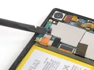
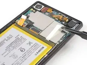
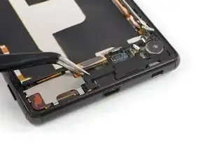
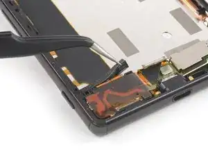
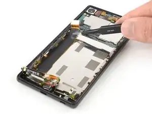
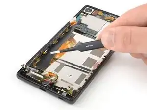
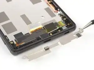
    • Insert one arm of the tweezer into the gaps between antenna cable routing and midframe.

    • Loosen the clips along the antenna cable on the right side of the midframe by gently twisting the tweezers sideways until the cable routing pops out of the clips.

  26. r215wU1QRXwHQcy2
    r215wU1QRXwHQcy2
    mBa3qB6Fkq2B1FQm
    • Use a pair of tweezers to peel up the main flex cable and separate it from the midframe.

    • In case you're having trouble to separate the main flex cable from the mid frame you can place an iOpener onto the display to loosen the adhesive underneath the flex cable.

  27. 6aFElrBX2Ari2NFY
    6aFElrBX2Ari2NFY
    KGZjKhdVbx5LlREe
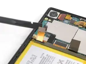
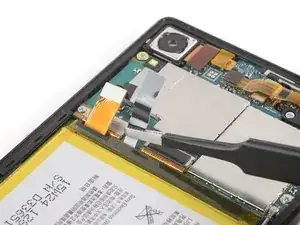
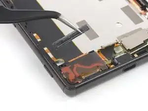
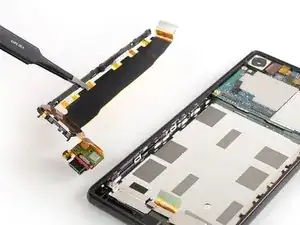
    • Use a pair of tweezers to remove the main flex cable assembly including the vibration motor and the microphone.

  28. mXK4JNZCVfdRtCFI
    mXK4JNZCVfdRtCFI
    1qlEDwyBLqCUHIoh
    • Unhook and remove the metal shield above the loudspeaker cover located at the bottom left.

  29. sPZZRaeyL1dlexVt
    sPZZRaeyL1dlexVt
    BSK4rB1g52w1aYfv
    • Peel off and remove the foam pad next to the loudspeaker cover.

  30. 3BJlQ1rSmoYFaAeM
    3BJlQ1rSmoYFaAeM
    BKc3WeHAZhGR4QrO
    • Also remove the plastic safeguard between the midframe and the loudspeaker cover.

  31. 2TVrUjNgBlPuN433
    2TVrUjNgBlPuN433
    Ss21XlC1HNa1kLnQ
    • Use a pair of tweezers to pry up the loudspeaker cover.

    • Fold the loudspeaker cover upwards until you have enough space to remove the loudspeaker in the next step.

  32. p4FpCS1eLap3dKTZ
    p4FpCS1eLap3dKTZ
    PsVmAQLXZlCS3aRi
    • Use a pair of tweezers to lift the loudspeaker out of its recess and remove it.

  33. bddMNVfrFdLKbyRH
    bddMNVfrFdLKbyRH
    FGTMSrCCGgOLoL4C
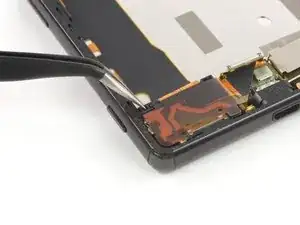
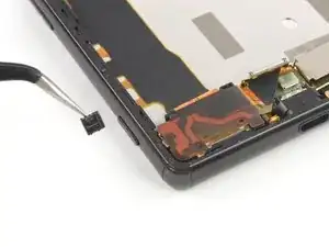
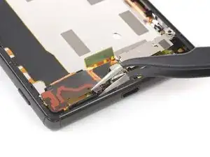
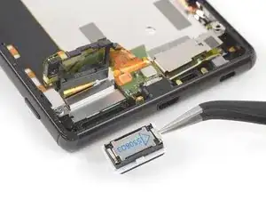
    • Use a pair of blunt nose tweezers to grab the flex cable between the charging port and the loudspeaker cover.

    • Carefully pull the charging port out of its housing.

  34. yXwCDTbXD1jNN6hk
    yXwCDTbXD1jNN6hk
    pRYcMCL6jFXEQny3
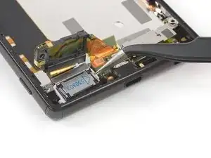
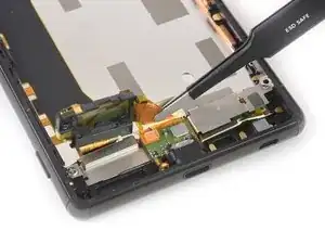
    • Use a spudger to pry up and disconnect the side button flex cable on the left side of the motherboard.

  35. etIJO1C61JWdpZVp
    etIJO1C61JWdpZVp
    MCeCRP5dPwsm1KdU
    VMGFo6I5keQu4dSV
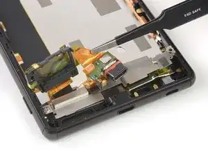
    • Use a pair of tweezers to loosen the plastic clips along the side button flex cable on the left side of the midframe.

  36. IBookJdu5RwoLHKE
    IBookJdu5RwoLHKE
    sje6MPIcxUwHuayB
    c2PgnaE1YrL3iJXA
    • Peel up the side button flex cable and separate it from the midframe.

    • In case you're having trouble separating the side button flex cable from the midframe you can place an iOpener onto the display to loosen the adhesive underneath the flex cable.

    • Remove the side button flex cable including the loudspeaker cover and the charging port.

  37. pSKtYYKQeGOlxj5V
    • Remove the Phillips #00 screw (2.4 mm length).

  38. eB3DKTx1pC1KFi3E
    eB3DKTx1pC1KFi3E
    3xIxAmZqSDmZysXU
    • Use a pair of tweezers to unhook the metal shield on top of the display cable assembly and remove .

  39. AyMYEtumGMjMTYcX
    AyMYEtumGMjMTYcX
    sHMMmcVUEQJFacOK
    lFZgL1GtZtXHORKN
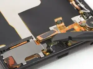
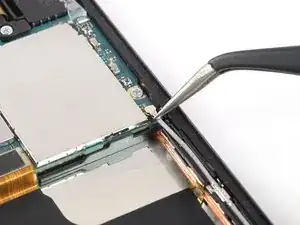
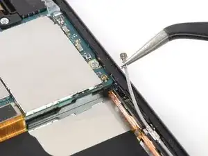
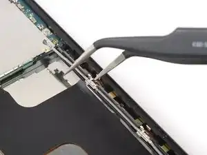
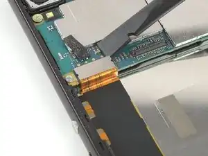
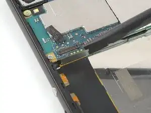
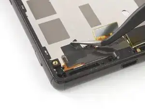
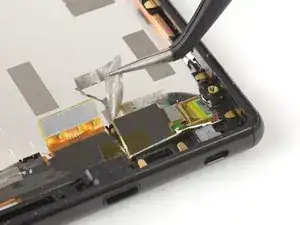
    • Use a pair of tweezers to peel off the black adhesive on the left side of the display cable assembly.

    • Also remove the silver adhesive strip on the right side of the display cable assembly.

  40. J4NsE1MwLAZb12vF
    J4NsE1MwLAZb12vF
    AbGIYnMlGg5rwsWM
    GbSlfHKZtAHOU3CT
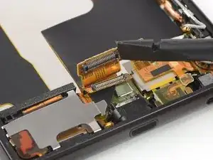
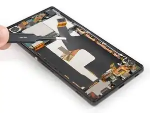
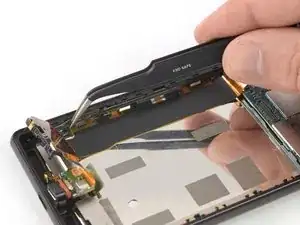
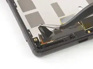
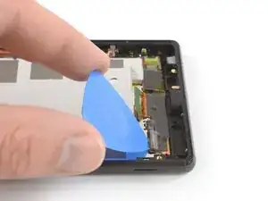
    • Get an opening pick under the left side of the display cable assembly.

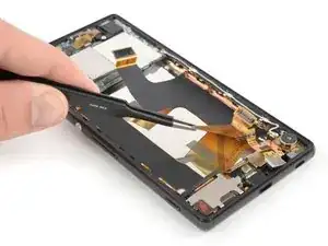
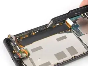
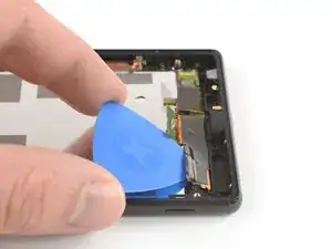
    • Use the opening pick to pry up the display cable assembly.

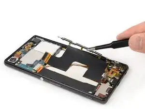
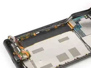
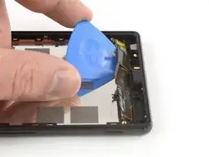
    • Carefully slide the opening pick from left to right to separate the display cable assembly from the midframe.

  41. 5pJcTTkXRssPqF2U
    • Apply a heated iOpener to the display for two minutes to loosen the adhesive beneath.

    • The adhesive that holds down the screen is fairly strong. You might need to reheat and reapply the iOpener several times to get the adhesive warm enough.

  42. XLM3M2SdZlrYoWIb
    XLM3M2SdZlrYoWIb
    DXbIiSsMmiiREqp2
    PmQsHX6RUiXh3Vgk
    • Apply a suction handle near the top edge of the phone right under the earpiece speaker.

    • If the phone's screen is cracked, the suction handle may not stick. Try lifting it with strong tape, or superglue the suction handle in place and allow it to cure so you can proceed.

    • Use the suction handle to pull up the screen and insert just the tip of an opening pick under the right edge of the speaker recess.

    • Slide the opening pick to the top right corner to loosen the adhesive.

    • Leave the opening pick in its position to prevent the adhesive from resealing.

  43. JfmgiPHiXpnUZtOM
    JfmgiPHiXpnUZtOM
    P56bxluSMftCaD3D
    3o4MTLWEMIdaPNZL
    • Insert a second opening pick at the top right corner of the screen.

    • Slide the opening pick along the midframe to loosen the adhesive under the right edge of the screen.

    • Leave the opening pick in the bottom right corner to prevent the adhesive from resealing.

  44. HCssIrRv5PIULWGr
    HCssIrRv5PIULWGr
    3tHxV2AFPtgo6glS
    • Apply more heat if the adhesive becomes hard to cut.

    • Insert a third opening pick under the bottom right edge of the screen.

    • Slide the opening pick to the bottom left corner to loosen the adhesive underneath the screen.

    • Leave the opening pick in the bottom left corner to prevent the adhesive from resealing.

  45. ssci46KsX2spflom
    ssci46KsX2spflom
    huOZsRwkLLrpRUTt
    s36QHF35TqlEEHEZ
    • Insert a fourth opening pick under the bottom left edge of the screen.

    • Slide the opening pick along the midframe to loosen the adhesive under the left side of the screen.

    • Slide the opening pick around the top left corner of the screen to loosen the remaining adhesive.

    • Try not to remove the display all the way yet. The display flex cable is still threaded through the midframe.

  46. YysDRYB14xGtJ62t
    YysDRYB14xGtJ62t
    qtH6BtQF2wxhOnyT
    QFuNCXYPgoetUFgt
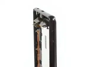
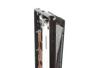
    • Slowly separate the screen from the frame and cut any remaining adhesive. Make sure the flex cable is no longer stuck to the frame and carefully thread it through its gap.

    • Remove the screen.

  47. bhrTgWBxZ3aQCuUy
    • Remove any remaining adhesive from the midframe, and clean the glued areas with isopropyl alcohol and a lint-free cloth before installing a new screen.

Conclusion

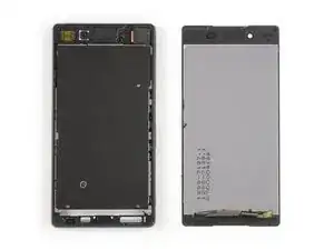
The best way to secure the new screen is with a sheet of custom-cut double-sided tape. Apply the tape to the back of the screen, then carefully feed the display cable through the frame. Align the screen and press it into place.

If possible, turn on your phone and test your repair before installing new adhesive and resealing the phone.

To reassemble your device, follow these instructions in reverse order.

Take your e-waste to an R2 or e-Stewards certified recycler.

Repair didn’t go as planned? Check out our Answers community for troubleshooting help.

Dominik Schnabelrauch

Member since: 23/11/16

224647 Reputation

0 comments