Introduction
Use this guide to return functionality to the 'hand crank' of your SolaDyne LED Lantern Hand Crank.
The hand crank is not necessarily the broken part in question this guide is addressing, but it is the crank dynamo behind the hand crank. The crank dynamo is the part that allows the generation of an electrical current via rotating a loop of wire between two permanent magnets, which then charges the battery which then powers the lantern, in turn producing light. Note where the hand crank in the device diagram is in this document for clarification.
Crank dynamos tend to come with an already attached hand crank, to clear up any confusion about the naming, and not every crank dynamo comes in the same shape and size as the one in this lantern, so do expect the risk of a potential misfitting should you purchase a new crank dynamo. The crank dynamo you will be replacing in this guide is not physically attached to the hand crank, so please purchase one that only comes with plugs, preferably the exact one the lantern has or you will have to do some DIY handiwork in attaching the crank dynamo to the body, as well as to the hand crank, which is not covered in this guide.
This guide involves the unplugging of the crank dynamo from the main power board which is connected to the battery to safely replace the crank dynamo in steps 5 to 7, however there are only two 3.6V batteries, so even with an exposed wire there is no risk of electrocution occurring in the worst case scenario of contact with a potentially exposed wire. While it may seem obvious, please do not have the lantern plugged in while doing this guide, and preferably not under the sun either as the top of the lantern has a solar panel installed.
Parts
-
-
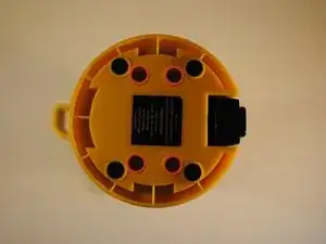
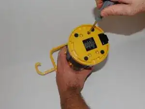
Flip lantern upside down and unscrew the 4 phillips head screws on the base and remove the base plate.
-
-
-
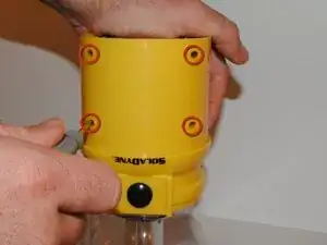
Slide the black rubber sleeve off of the outside of the body of the lantern away from the LED globe.
-
-
-
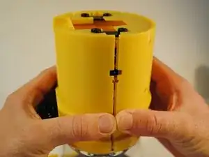
To disassemble the main body, grip the lantern so that the front half of the body with the power button on it is in your right hand and the back half with the hand crank is in your left.
-
Pinch the front half of the body on both sides with your thumb and index finger just below the first extruding rim of the front plate while simultaneously pulling the back half away. This may take some effort to do.
-
Take note to remove and set aside black screw mounts located in between the halves at the bottom of the lantern.
-
-
-
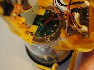
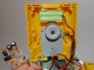
Locate the crank dynamo component. It is mounted on the back plate directly above the battery.
-
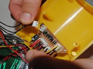
Trace the wires from the dynamo component to the main power board. Pull out the white clip from the socket on the main board. This will sever the electrical connection between the crank dynamo and the rest of the lantern.
-
-
-
Locate the DC-in board. It is mounted onto the back plate slightly covering the bottom right corner of the crank dynamo.
-
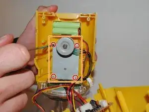
Remove the two screws mounting the DC-in board.
-
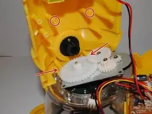
Move the DC-in chip out of the way in order to access the crank dynamo.
-
-
-
Unscrew the four screws mounting the crank dynamo component to the back plate.
-
Remove the crank dynamo from the lantern.
-
-
-
Place new crank dynamo where the old one was previously housed on the back plate. Make sure to align screw holes on the dynamo to those on plate.
-
Replace the four screws holding the dynamo in place.
-
Attach the wires from the new crank dynamo to the correct area of the main board where the old wires were removed.
-


To reassemble your device, follow these instructions in reverse order.