Introduction
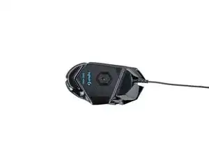
This guide demonstrates how to remove the side buttons board from the Logitech G502 Hero.
-
-
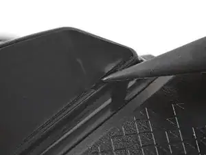
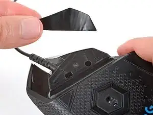
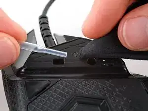
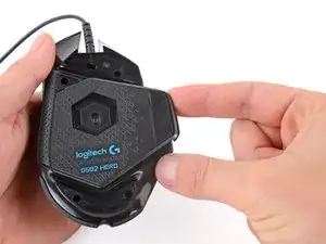
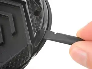
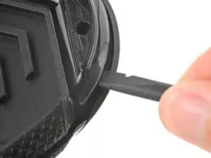
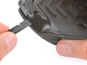
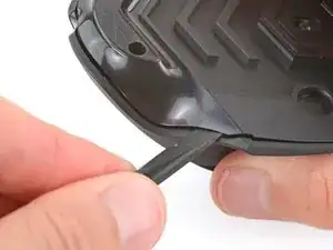
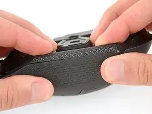
Carefully slide the point of a spudger under the large foot near the front of the mouse, making sure it goes under both the foot and its adhesive pad.
-
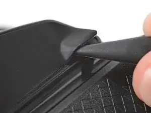
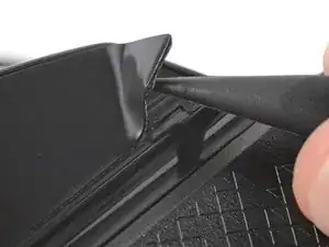
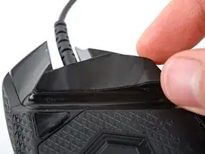
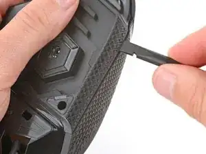
Gently slide the spudger farther under the foot and lift until you can grip the pad with your fingers.
-
-
-
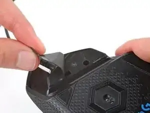
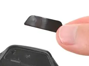
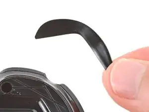
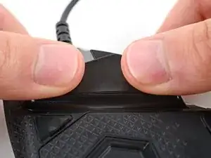
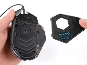
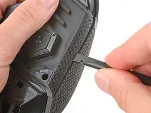
Peel up and remove the foot.
-
If the rubber layer separates from its adhesive pad, use the same process to remove the pad.
-
-
-
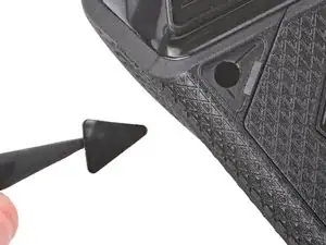
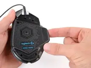
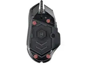
Use a spudger to carefully scrape up and remove any remaining adhesive bits.
-
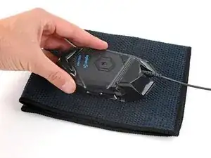
Use isopropyl alcohol and a microfiber cloth to thoroughly clean all adhesive residue from the foot recesses. Allow the surface to completely dry.
-
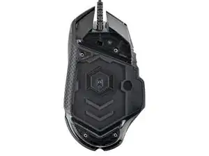
Remove the feet from their backing and firmly press them into place.
-
-
-
Lift the weight door by its tab and remove it.
-
If you have weights in the compartment, remove them.
-
-
-
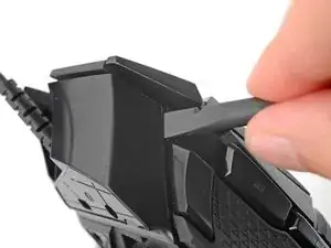
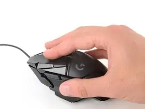
Insert the flat end of a spudger between the top and bottom shells, near the back of the mouse.
-
Twist the spudger to unclip the shells.
-
-
-
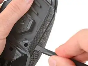
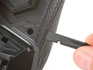
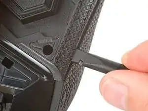
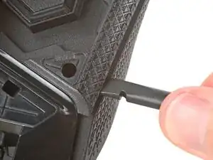
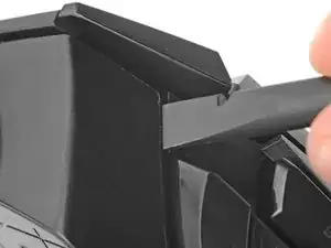
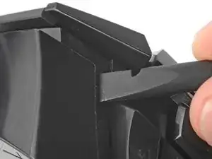
Insert the flat end of a spudger between the textured edge of the top and bottom shells, near the back of the mouse.
-
Slide the spudger towards the front of the mouse and intermittently twist, stopping near the screw hole.
-
Leave the spudger inserted for the next step.
-
-
-
Insert the flat end of a spudger between the top and bottom shells, near the back of the mouse.
-
Slide the spudger towards the thumb rest and push in to unclip the shells.
-
-
-
Insert the flat end of a spudger between the top and bottom shells, near the G8 and DPI shift (⊕) buttons at the front of the mouse.
-
Pry up with the spudger and push the shells apart to unclip them.
-
-
-
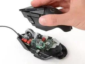
Lift the top shell straight up and remove it, making sure the main mouse cable stays attached to the bottom shell.
-
-
-
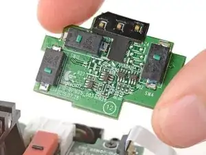
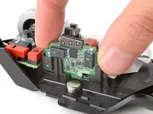
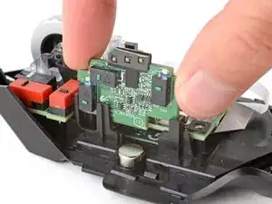
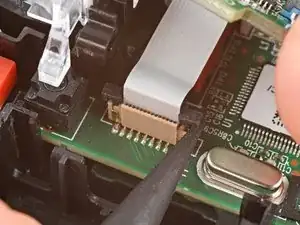
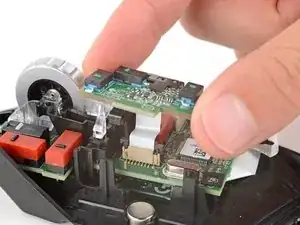
Hold the button board out of the way so you can access its connector on the motherboard.
-
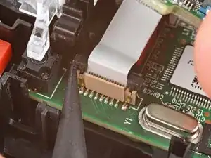
Use the point of a spudger to push up on alternating sides of the connector's plastic latch until it's in the unlocked position.
-
-
-
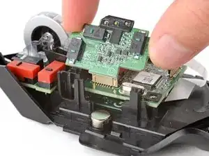
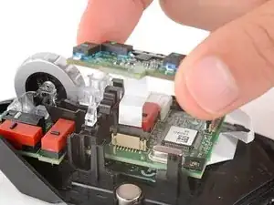
Gently pull the board straight up so the cable comes out of its socket.
-
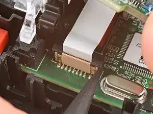
Insert the cable into its socket so the blue tab is on the same side as the connector's latch.
-
Use the flat end of a spudger to push the latch straight down into its locked position.
-


To reassemble your device, follow these instructions in reverse order.
