Introduction

Hey Momo here showing you how to service and maintain your Wii disc drive! This guide only goes for the original models with GameCube as far as I know but I'm sure a lot of the steps can be used for reference here. I'm not going to cover opening your Wii as there's already great guides on here for those and much more, but when it came to the OEM disc drive I just saw the option to "replace" the disc drive instead of opening up and cleaning it. In my experience the drives are relatively straightforward and I believe with my photos to reference you for avoiding mistakes I made on a practice drive, you should have your drive working perfectly in no time!

  1. unHnsKZaWIMIMEUP
    unHnsKZaWIMIMEUP
    hsjq1KwUCVUCmepd
    JZZTZMpXQkWe2A3T
    • Disconnect all external cords from the Wii console.

    • Gather all tools.

  2. DTTHDeSLkpioVpWM
    DTTHDeSLkpioVpWM
    vVq2YYS2PMatTXw6
    NVtGKlFdtZVdIcnJ
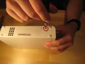
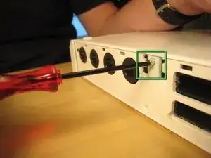
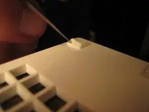
    • One small screw holds the BIOS memory battery.

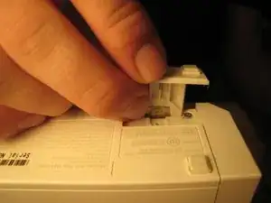
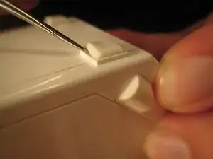
    • Once that screw is removed, you can slide out the plastic slot.

    This doesn’t specify which screwdriver to use

    Kilo -

    I used a Philips Head 00 and it worked great!

    Foster Savitsky -

    Once battery is removed, is all save data list? Probably should copy to SD card, just in case data list list from battery removal.

    pvman -

  3. qIGGjlI23SOLbUMw
    qIGGjlI23SOLbUMw
    6vLY2BxsyjsWer5X
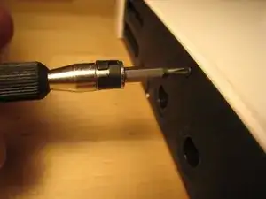
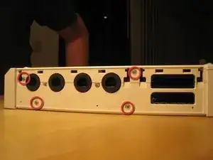
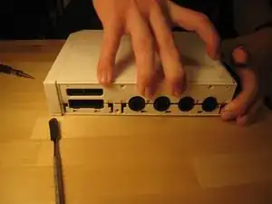
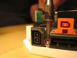
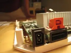
    • Remove these three black case screws. The one on the right is a few mm longer. These screws hold on the black plastic cover for the GameCube ports.

    Philips 00 worked

    Foster Savitsky -

  4. QvHBQwTcSGFNmVrA
    QvHBQwTcSGFNmVrA
    tfvPFmimBO1KCa6N
    • Lift off the black plastic plate.

    • There are four screws: two Phillips #00 and two Tri-Wing.

  5. ecO2LKWTXkyooSXx
    ecO2LKWTXkyooSXx
    uKSAOFcEySugBGtV
    DPcEJNjUrp5ABuEl
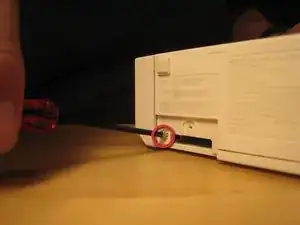
    • Remove all screws from the case.

    • Some screws are under rubber feet, or small, square paper screw covers (red square). I used a sharp metal tool to get under the screw covers. You could use an X-acto knife.

    • Several case screws require a Tri-Wing screwdriver.

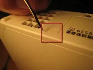
    • The next step has more pictures of removing rubber feet and the screws underneath. The feet and screwcovers are self-adhesive, but not every foot or screwcover has a screw.

    What tri wing screwdriver size i need?

    Panapleyo Pana -

    I used Y1 in the ifixit kit

    Paul Young -

    Definitely this. The Y1. Those tri wing screws under the stickers on the bottom of the front bezel are in rather tight and anything too small might damage the head.

    Shannon B -

  6. nkokcneEvkgrRHDT
    nkokcneEvkgrRHDT
    L1BdMQj3BuyENGBa
    EWFsWc2p2EvErNVT
    • Remove rubber feet and screws underneath.

    The screws beneath the thick feet are very deep and therefore can't be loosened by a precision screwdriver with a bit. The precision screwdriver is barely too big to fit inside the screwhole.

    Levin Klaiber -

    If you have the size 4 socket bit you can use it as a narrow extender

    ZEDZANO -

    There are no screws under the two rear rubber pads on the serial number side of my RVL-001(AUS) Wii. I don't know why the author photographed themselves removing those rubber feet. Only remove the rubber pad near the front on that side (as well as the battery compartment, and the screws mentioned in step 4) to get the front bezel off.

    Shannon B -

    I found this helpful teardown vid which shows all the screws you have to remove: https://www.youtube.com/watch?v=80DvlAE8...

    Shannon B -

  7. QO2CQ5LlBVwt524C
    QO2CQ5LlBVwt524C
    4p2JXCL6BPNQ4lbZ
    PkOWI4i3ROfOVWqT
    • Careful! If you don't remove the feet and the screws underneath before you try to pull off the front panel, the tab can split!

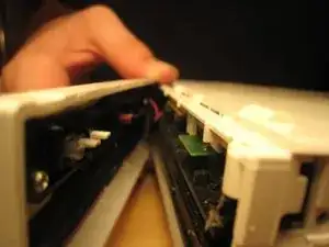
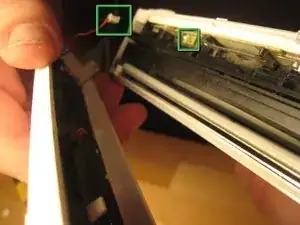
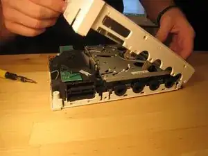
    • Once all screws are removed, you should be able to pull off the front drive panel.

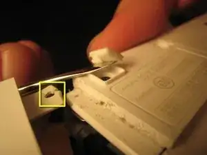
    • The wire connecting the front panel (green squares in the third image) can be pulled out gently by hand or with the help of a spudger.

    If you actually take the time to do this step It would not have a broken holder

    Walker wallace -

    I was not gentle enough in removing the plastic wire connector. The red wire broke off, with a small piece of the red wire stuck in the plastic connector. I really can't get the small piece of red wire out of the connector.

    Anyone know of anywhere that sells a connector, or at least what the name of kind of connector is?

    Bronze Owl -

  8. jeKYSNNIH2Y3YEo3
    jeKYSNNIH2Y3YEo3
    4WevAdL4utLPrhHm
    tOVCL4oBjmByVKNL
    • Now the case can be pulled apart.

    You forgot to mention the metal piece that you have to remove before you hit the 6 screws

    tommyb345 -

    I see that it was attached to the plastic shell in yours. Mine was not it was clipped into the drive.

    tommyb345 -

  9. Gd25XvKBphbeDbxB
    Gd25XvKBphbeDbxB
    esOmlIMdV1huN1wc
    CH3ND6YONBAwFhAl
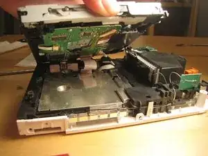
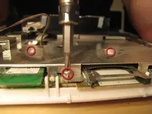
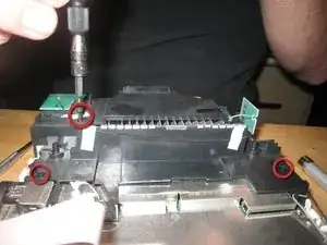
    • We lifted up the cover of the optical drive by removing the six Phillips #00 screws. These are all labeled on the previous image.

    • Because of a secured wire leading to the drive, we reattached the cover to facilitate the remove of the entire drive assembly without harming any of the electronics.

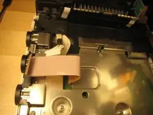
    • There are a ton of parts in the optical drive, but there is nothing very fancy about this drive compared to other slot-loading drives, so I didn't take it apart completely. There are also a ton of gears and levers that I did not want to deal with.

    The six Phillips screws are only holding in the optical drive, so if you only need to take the case off, the sides of it are just very snug against the inside wall and other components

    Jace Holmes -

    I had a small spring fall out at this step. It went right next to the motor by the actual spiral part of it going on a small black stud while one end of it goes under the white plastic piece by it, and the other end of it gets kind of held by the black plastic frame. It’s hard to describe, but it can be faintly seen in the bottom middle of the third image in this step.

    Jadon Savell -

    Mine had only 5 screws for this step

    Shannon B -

  10. ECb6mKIVQftAhvkT
    ECb6mKIVQftAhvkT
    HFFgxM6CTA62lQpi
    aCGbX1vYde6XW4XJ
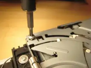
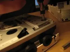
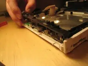
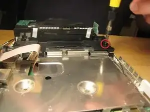
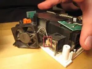
    • The screws holding in the drive were deep within the casing.

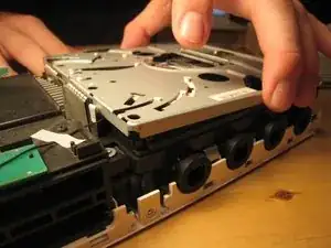
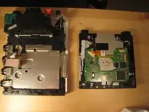
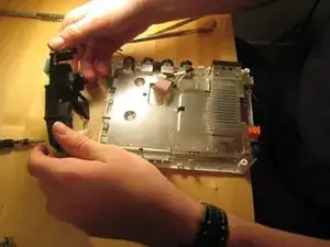
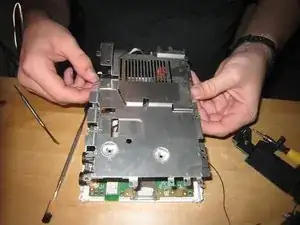
    • Once those screws were removed, the entire case could be lifted off.

    • Don't pull too hard! There are two cables attaching the drive to the logic board underneath.

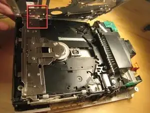
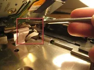
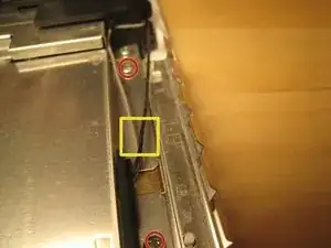
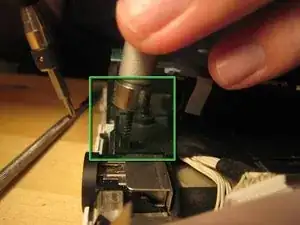
    • This wire slid out from its horizontal slot. Once it was detached, the ribbon cable came out as well.

    The connector for the ribbon cable has a lock. The grayish/brown top to the connector can be flipped up from the ribbon side and the ribbon cable then falls out. It is not designed to have the ribbon cable just pulled out. You should definitely flip it up to put the cable back.

    Dan O -

  11. YW4KmKZCucUTUkP4
    YW4KmKZCucUTUkP4
    4ymAE4efGYYlBwrI
    • With those wires detached, the optical drive came off completely.

  12. 4A1T4XA2kksJ4CEk
    4A1T4XA2kksJ4CEk
    pZGuQxLsgtOYKXMP
    • We begin trying to get to the logic board by removing this small black plastic rim.

    • Once within the case, all screws are Phillips #00. There are marked on the logic board with arrows, triangles, boxes, and crosses. From what I can tell, an arrow means that it just goes through the logic board cover. A triangle means that it is a longer logic board cover screw. A cross means that it holds on a plastic piece, and a box means that it holds on another EM shield / or heat sink.

    There is a small nut fitted snuggly on right side of the black plastic rim. Careful you don’t drop it and lose it.

    ghgomez1 -

    No worries, it fell out long before I got this far and I heard it bounce around inside. Set it aside once I got the lid off and it rolled out.

    It fits in this small stand-up slot that doesn't seem to hold the square nut in .. so a dab of white glue to keep it there while the work is going on did the trick.

    Minok -

  13. j4RQWMDxbJLZx6Lw
    j4RQWMDxbJLZx6Lw
    CiqmjHel65dtQXBN
    VndjpE5Hx4w1Nlhs
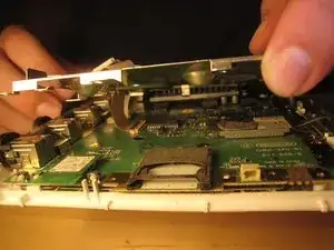
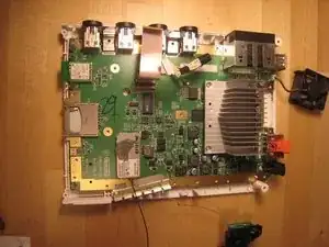
    • Remove all screws from the logic board cover. Two are recessed in the middle; others are along the edge. More will become visible as other parts are removed. It's like a game! You can start with the screws holding in the black plastic pieces, but I started with the most visible and went from there.

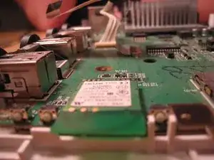
    • There are two wires (shown in the third picture) coming from the logic board and connected to the Wi-Fi antennas. These are delicate. Do not break them.

  14. PdKsymS6YPWtrWjk
    PdKsymS6YPWtrWjk
    AOCOPrTZOvXTaLXq
    • Take out these screws in the black plastic casing.

  15. 1j6GuTKUsaXBTANj
    1j6GuTKUsaXBTANj
    1vxCXyD5L6othpEe
    • Detach the case fan. There are two screws holding it in.

    • You must detach the power connector for the fan if you want to remove it completely.

    Under the fan was there a little aluminium part? Because I have this left over aluminium part and I have no idea where it goes

    Haley M -

  16. LWt2fSpvlLFIOSLn
    LWt2fSpvlLFIOSLn
    g5dIQZCYOl5Y4Vty
    • If your screwdriver is not magnetized, you will need a magnet to get out some of the embedded screws. You can hold a magnet against your screwdriver shaft to temporarily magnetize it.

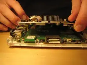
    • Once all the screws out, you can begin to remove the black casing.

  17. KnMRwiAJqbOGwVp3
    KnMRwiAJqbOGwVp3
    DYxB2YWsS41WqBCU
    gdqYg1TZjawD3JMZ
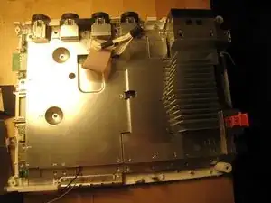
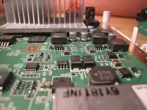
    • With the black plastic covers off, we can see all the screw holes. Most of the screws are out by now, but once the rest of them are out, you can lift off the logic board cover.

    • Note that at least one part is thermal padded to the logic board cover. You might have to replace this thermal pad, but I didn't. I just pushed them back together. Oh well!

    • Remove any remaining screws in the logic board cover.

  18. hcURPGipeusYNUP3
    hcURPGipeusYNUP3
    vBgU4LaevZdTRhki
    FDIuTWPJF1MDTMnE
    • Once all screws are removed, lift off the logic board cover.

  19. ewv3yZPOujCRpKEj
    ewv3yZPOujCRpKEj
    VbYIsqLnCjhNRTfF
    NCnsWFuHrKuw1QQO
    • Look around.

    • This is the thermal padding.

    • We opted not to remove the heat sink from the logic board, but it certainly could be removed.

  20. SsIM5NFbf3VUYQIr
    SsIM5NFbf3VUYQIr
    fgHENtI21AyZJoGE
    MUfZHTEfUeduR2At
    • Take some more awesome photos.

  21. 6wEh4GneCZvKSMlg
    6wEh4GneCZvKSMlg
    Km2bVE4nHWx5sIfj
    EXCEqyCwMZUgIhJE
    • And take a couple more photos.

  22. 6XhGqthv1FWe6mfU
    6XhGqthv1FWe6mfU
    HCNcvGJ5cOUOOB6V
    • We stopped there.

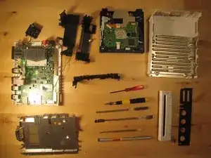
    • A muffin tin worked really well to organize all the screws.

    • Putting the Wii back together took only about half an hour, and it works perfectly. We improved Nintendo's design by three or four screws and one square nut, but worsened their design by one piece of duct tape (to hold in the bios battery).

    The extra Square Nut goes in the right hand side of the plastic bracket in step 12. It is the reason you ended up needing duct tape for the battery door.

    William Bennett Lapides -

Conclusion

Disassemble following that awesome person's guide to step 11. To reassemble the DISC DRIVE, follow these instructions in reverse order. To reassemble your WII CONSOLE, follow the above referenced guide in reverse order.

M0m0

Member since: 27/08/23

82 Reputation

0 comments